
User's Manual


Corning Optical Communications User Manual I CMA-336-AEN I Page 26
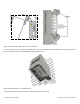
2. Using the mounting bracket top and bottom mounting holes as a guide (refer to Figure 3-6):
Measure and mark the location for drilling the (supplied) M10 Masonry bolts (Φ12) in the wall (six per bracket and drill
the holes).
Note: The GX quad-band unit is mounted vertically with the connectors facing downwards.
Using an electric drill with a Φ12 head, drill the holes for the Masonry bolts
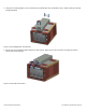
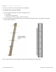
Figure 3-6. GX Mounting Bracket
3. Using six (M10 x 110) Masonry bolts per bracket – secure the mounting brackets to the wall with the protruding pins facing
towards you. The GX quad-band will be hung on these. See Figure 3-6.
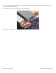
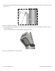
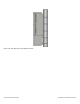
4. Connectors facing down, carefully fit and hang the GX unit on the Pins (see Figure 3-7) protruding from the top, and
middle-bottom parts of the mounting bracket.