
User's Manual


Corning Optical Communications User Manual I CMA-336-AEN I Page 21
3.1.2 Installation Procedure
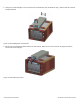
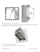
1. Remove the eight M4 socket cap screws on the GX side panel (adjacent to the RF jumper connections), using an Allen
wrench.
2. Remove the pre-connected RF jumper cable on the GX, using an adjustable wrench.
Figure 3-1. Removing GX Panel Screws
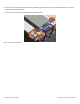
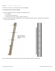
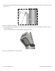
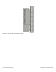
3. Fix the upper bracket and lower bracket onto the GX using eight of the provided M4 x 14 Torx Head Screws.
Figure 3-2. Assembling Filter Brackets