
User's Manual


Corning Optical Communications User Manual I CMA-336-AEN I Page 20
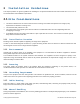
3 System Installation
This chapter describes the installation procedure for the GX quad-band remote units. The installation of the system
components must be in the following order:
1. External filter installation - only relevant for GX quad-band models supporting CELL band and which are deployed with
units supporting 800 MHz band. See section 3.1.
2. GX remote unit iInstallation. See section See section 3.2.
3. External combiner installation (optional). See section 3.3.
3.1 Installing External Filter (If Required)
External Filter (ordered separately) is required if GX is deployed along with units supporting the 800 MHz Public Safety band.
It is recommended to perform this procedure before the GX installation.
The installation procedure requires the following tools (not provided):
L-shaped size 3 Allen wrench
T20 Security Torx
Adjustable wrench (0 ~ 20 mm)
3.1.1 Package Contents
Unpack and inspect the cartons according to the following procedure
1. Open the shipping carton and carefully unpack each unit from the protective packing material.
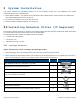
2. Please verify that the items listed in Table 3-1 are included in your package (image size is not proportional) and check for
signs of external damage. If there is any damage, call your Corning service representative.
Item
Quantity
Image
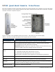
CELL/ESMR MHz Filter; 817 – 849 MHz; N-Type Male
1
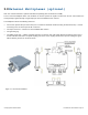
Upper Bracket (for GX Quad-band chassis)
1
Lower Bracket (for GX Quad-band chassis)
1
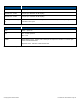
RF Cable - N-Type Female to N-Type Male jumpers; L= 10.62 in (269.74
mm); Used for GX filter connections
2
Grounding Wire - 6 AWG; L = 78.74 in (2000 mm)
1
Hexagon Cap Screw, (GB/T5783,M5×10)
2
Spring Washer (GB/T93,5)
2
Torx Head Screws Kits (for GX Quad-band chassis), (M4×14)
12
Table 3-1 External Filter Package Items