
User's Manual


Corning Optical Communications User Manual I CMA-336-AEN I Page 15
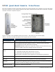
1.3 GX Quad-Band Remote Interfaces
All of the GX interfaces (except for the power connector) are located externally on the underside of the unit (facing down
when unit is mounted). The unit interfaces include the RF, power, optical link and external alarms connections. The power
connector is located in a separate side panel.
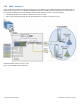
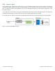
Figure 1-6. Example of GX Quad-Band Remote (AC) Interfaces – Side Panel (Left) and Underside (Right)
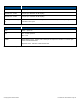
Table 1-1 and Table 1-2 provide descriptions of the GX-Quad connectors and LEDs.
Interface
Description
Service Connectors
Service specific RF DIN female connectors to antennas (or external combiner)
OP
Corning OptiTap™ fiber-optic waterproof connector – connects to OCH-GX-XR using
Corning OptiTap to SC APC cable (ordered separately).
IMPORTANT! OptiTap™ pullout force ranges from a few lbs to 50+ lbs with the dust cap or
connector installed. This prevents damages caused to the DAS unit.
Power Connector (side
panel)
Power feed option is model dependent:
Local power feed (AC) option: 100-240 V AC; 47-63 Hz;
Remote power feed (DC) option: 40-57 V DC ; Max 37.5A
Maximum power consumption: Refer to Appendix A for detailed power specifications
LAN
RJ-45 connector for local connection (i.e., debugging, troubleshooting)
EXT_ALM
External Alarm pin-out connectors supporting four external alarm connections
SYS_ALM
Pin-out connector supporting up to three relay alarms used for connecting the GX-QUAD to
a network or modem and relaying the status of the GX alarms
1900MHz CPL -50 dB
Coupler port 1900 MHz 50 dB coupling