
User's Manual


Corning Optical Communications User Manual I CMA-336-AEN I Page 11
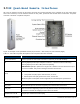
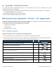
1.1 System Architecture
GX provides a complete solution consisting of GX-Quad remote units at the remote locations, and head end elements, which
are shared with any existing or new MA1000/MA2000 deployment. GX consists of a uniquely designed, non-obtrusive unit
that includes all of the required RF, fiber optic and power interfaces. All mobile services are distributed through service/band
dedicated RF connection ports over antennas installed at the remote locations.
IMPORTANT! GX quad-band models GX-E17E85P19L70-40-AC and GX-E17E85P19L70-40-DC do not support coexistence
with other GX models. These must be connected to a different RIU or different sector (for RIU-12) and to a different optical
module of the OCH. Connecting these GX models to the same RF paths as other GXs may result in a VSWR alarm.
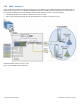
1.1.1 SISO Scenario
Figure 1-2 illustrates a scenario including one GX quad-band remote and one GX tri-band remote. Note that all site elements
are managed and controlled via a single SC-450 controller (software version 5.4 and higher) that enables local and remote
management, and provides single-source, centralized common headend controls of all installed elements.
For the GX path, at the headend, the BTS or BDA signal is conditioned by the RIU, ensuring a constant RF level. The
conditioned RF electrical signal is then converted by the optical central hub (OCH) to an optical signal for transport to/from
multiple GX remotes, over low-loss fiber cabling.
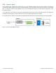
*In installations including a GX supporting the CELL band and a GX supporting the Sprint800 band, the CELL and Sprint service
signals must be conditioned via two independent sectors in the RIU-12 (i.e., SectorA and SectorB in Figure 2) and routed through
dedicated optical modules in the OCH. Note the following:
Installations with RIU-4 units require a dedicated RIU-4 per GX model
Either an OCH-4 unit per GX or an OCH-8 (supporting two separate optical modules) is used
**External Combiner Insertion Loss of 1.0 dB
Figure 1-2. GX SISO Architecture