
User's Manual

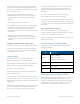
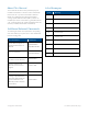
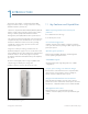
Table Of Contents
- 1 1Introduction
- 2 2Installation Guidelines
- 3 3System Installation
- 3.1 Selecting GX Dual-Band Mounting Location
- 3.2 Unpacking and Inspection
- 3.3 Additional Required Tools
- 3.4 Required Headend Connections for Deployments with Corning® Optical Network Evolution (ONE™) Solution
- 3.5 Outdoor Concrete Wall-Mountable Installation
- 3.6 Additional Installation Options
- 3.7 GX Connections
- 3.8 Verifying Normal Operation
- 4 4Appendices

Corning Optical Communications User Manual
|
CMA-601-AEN
|
Page 5
About This Manual
This user manual describes how to perform the physical
installation and interface connections of the GX dual-band
remote unit. The scope of the user manual includes the
interface box (IFB) required for deployments with the
Corning® optical network evolution (ONE™) solution. The
installation procedures of other units (e.g., HEU/IHU, IFB, RIU,
OCH, SC-450) relevant to the system are detailed in their user
manuals (see Additional Relevant Documentation).
Additional Relevant Documents
The following documents are required if the corresponding
units are included in your system. These can be downloaded
from the Corning portal.
Document Name Part Number
RIU Product Family (RIU-4,
RIU-IM, and RIU-Lite) User
Manual
709C007703 Rev.
A00/CMA-139-AEN
RIU-12 User Manual
709C011602 Rev.
A00/CMA-334-AEN
FT350 Installation Guide
(includes OCH information)
CMA-208-AEN
System Controller User
Manual (SC-450 v7.4 and
higher)
CMA-456-AEN
IFB Quick Installation Sheet —
Corning® Optical Network
Evolution (ONE™) Solutions
System Installation User
Manual (includes HEU/IHU
information)
CMA-490-AEN
List of Acronyms
Term Meaning
BTS Base transceiver station
BTSC Base transceiver station conditioner
DL
Downlink
GX Greater-power unit
HEU Headend unit
IFB Interface box
IHU Integrated headend unit
OCH Optical central hub
RIU Radio interface unit
UL Uplink