
User's Manual

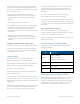
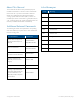
Table Of Contents
- 1 1Introduction
- 2 2Installation Guidelines
- 3 3System Installation
- 3.1 Selecting GX Dual-Band Mounting Location
- 3.2 Unpacking and Inspection
- 3.3 Additional Required Tools
- 3.4 Required Headend Connections for Deployments with Corning® Optical Network Evolution (ONE™) Solution
- 3.5 Outdoor Concrete Wall-Mountable Installation
- 3.6 Additional Installation Options
- 3.7 GX Connections
- 3.8 Verifying Normal Operation
- 4 4Appendices

Corning Optical Communications User Manual
|
CMA-601-AEN
|
Page 4
installed to provide a separation distance greater than 400
cm or more from all persons during normal operation and
must not be co-located with any other antenna for meeting
RF exposure requirements.
•
The design of the antenna installation needs to be
implemented in such a way so as to ensure RF radiation
safety levels and non-environmental pollution during
operation.
•
Antenna gain should not exceed 12.5 dBi.
•
Each individual antenna used for this transmitter must be
installed to provide a separation distance greater than
400 cm or more from all persons and must not be
co-located with any other antenna for meeting RF exposure
requirements.
•
The design of the antenna installation needs to be
implemented in such a way so as to ensure RF radiation
safety levels and non-environmental pollution during
operation.
Compliance with RF safety requirements:
•
Corning products have no inherent significant RF radiation.
•
The RF level on the downlink is very low at the downlink
ports. Therefore, there is no dangerous RF radiation when
the antenna is not connected.
Laser Safety
Fiber optic ports of the GX system emit invisible laser
radiation at the 1310/1550 nm wavelength window.
The laser apertures/outputs are the green SC APC bulkhead
adapters located on the front panel of the equipment.
The product is Class 1/Hazard level 1.
External optical power is less than 10 mW, Internal optical
power is less than 500 mW.
To avoid eye injury, never look directly into the optical ports,
patch cords, or optical cables. Do not stare into beam or view
directly with optical instruments. Always assume that optical
outputs are on.
Only technicians familiar with fiber optic safety practices and
procedures should perform optical fiber connections and
disconnections of GX devices and the associated cables.
GX has been tested and certified as a “Class 1” Laser product to
IEC/EN 60825-1(2007). It also meets the requirements for a
Hazard Level 1 laser product to IEC/EN 60825-2: 2004 to the
same degree.
GX complies with 21 CFR 1040.10 and 1040.11 except for
deviations pursuant to Laser Notice No. 50 (2007).
The product itself has been tested and certified as a Class 1 Laser
product to IEC/EN 60825-1 (2007). It also meets the requirements
for a Hazard Level 1 laser product to IEC/EN 60825-2: 2004 to the
same degree.
Care of Fiber Optic Connectors
Do not remove the protective covers on the fiber optic
connectors until a connection is ready to be made. Do not leave
connectors uncovered when not connected.
The tip of the fiber optic connector should not come into contact
with any object or dust.
Standards and Certifications
Corning products have met the approvals of the following
certifying organizations:
Category Standards
Safety:
CB: IEC 60950-1;
NRTL: UL 60950-1;
CAN/CSA: C22.2 NO 60950
EMC: FCC: Part 15 subpart B
Radio: FCC: Part 27
ISO: ISO 9001: 2000 and ISO 13485: 2003
Licensee Contact Information
Industrial Boosters may only be used by FCC licensees or those
given express (individualized) consent of license. Corning
certifies all of the VARs listed as licensed installers for Corning.
For the list of licensed VARs, please contact the Corning Tech
Support Hotline: (US) 410-553-2086 or 800-787-1266.