
User's Manual


Appendix B: Ordering Information
MobileAccessGX Installation and Configuration Guide 48
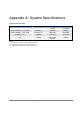
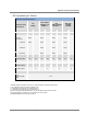
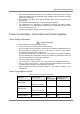
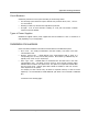
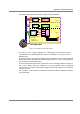
The following figure illustrates fiber optic routing to Remote Cabinets.
Figure 4-7. Illustration of Fiber Optic Routing
• For remote power supply configuration - cable bundles are routed from the main
communication room and individual wire pairs are terminated into the power feed of
individual units.
By providing power from a single distribution point, maintenance can be reduced and UPS
backup can be easily provided. The maximum distance from the source to the termination
spot is 1000 feet using 18 gauge wires.
In many locations local codes do not require power to be run through conduit if 100 watts or
less is used. Please consult the regulations in your local jurisdiction prior to deploying
remote power. When power cables require distances greater than 1000 feet 14 or 16 gauge
wire may be used.
• On each floor - the antennas are connected to the Remote Cabinet or MA2000-Lite system
using coax cables.
Optical Cable
RC
Port 1
Port 2
Port 3
Ant.
1
Ant.
2
Ant.
3
Load
50 ohms
RC
RC
Floor 3
Floor 2
Floor 1
Fiber Optic Cables
8-Strand Fiber Cable
Assembly
(2 spare for
additional RUs)
Splice Box
Port 4
Splice Box
Splice Box
Fiber opt. In
Fiber opt out
Fiber opt. In
Fiber opt out
Fiber opt. In
Fiber opt out
Optical CableOptical Cable
RC
Port 1
Port 2
Port 3
Ant.
1
Ant.
2
Ant.
3
Load
50 ohms
RC
RC
Floor 3
Floor 2
Floor 1
Fiber Optic Cables
8-Strand Fiber Cable
Assembly
(2 spare for
additional RUs)
Splice BoxSplice Box
Port 4
Splice BoxSplice Box
Splice BoxSplice Box
Fiber opt. In
Fiber opt out
Fiber opt. In
Fiber opt out
Fiber opt. In
Fiber opt out