
User's Manual


Installation – Digital Coverage
Elements
P/N 709C011801 Page 51
5 Ins tallation – Digital Coverage Elements
This chapter describes the installation of the Digital Coverage components. It contains only brief descriptions of the approach of
each installation procedure. For step-by-step installation descriptions refer to the Quick Start Guides provided with the ordered
units, and for specific guidelines on infrastructure planning, design and installation, please consult with a Corning Product Line
Manager or Corning approved Installer. All these elements are installed at the remote end.
5.1 CEU Installation
General Information
• The CEU interfaces to the main Ethernet switch and to the remote Gigabit Ethernet Modules (GEM).
• The CEU is rack mounted or wall mounted at the IDF (Intermediate Distribution Frame).
• The CEU can host up to 3 CEM (Centralized Ethernet Modules), which are not included in the CEU package.
• The CEM Tx/Rx Ethernet fiber ports, used for interfacing to the GEM modules, require SFP modules (included) and LC-UPC
to LC-APC adapter.
To install the CEU
1. Install CEM modules in the CEU chassis.
2. Mount CEU chassis - rack mount or wall mount
3. Connect CEM to main LAN (Ethernet switch).
4. Con
5. nect fiber – fiber connections between CEU SFP modules and GEM modules.
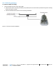
Figure 5-1. CEU Ethernet and Fiber Ports
6. Power up – using 110-240VAC power cable.
7. Verify normal operation - via F/O, ETH and PWR status LEDs.