
User's Manual


Installation – RF Path Elements
P/N 709C011801
Page 49
4.2.2 RAU Installation
4.2.2.1 General Information
• The RAU modules are deployed on the floor level and interface to the RF antennas.
• The RAU can be provided in a number of configurations:
• RAU (without RxU and GEM)
• RAU + RxU
• RAU + GEM
• RAU + RxU + GEM
NOTE: Existing RAU units can be upgraded with RxU and/or GEM modules – relevant Quick Start Guide with installation
instructions are provided with ordered units.
• The RAU supports various mounting installation options: wall/ceiling/acoustic ceiling
If the RAU is installed below or mid-mount an acoustic ceiling, a support bar (T-Bar) is required (not included).
Acoustical Ceiling grid work is not designed to support the weight of the enclosure.
• RAU optic fiber connections and DC power are provided via a Corning Composite cable (ordered separately).
To install the RAU
1. Locate fiber and DC connections cables - Corning Composite cable wiring leading from ICU.
NOTE: RAU units that include GEM modules, require additional DC wire for Secondary Power connection and Ethernet.
2. Mount the installation bracket according to one of the following installation options:
• Wall-mount: mount bracket on wall
• Concrete/Above Acoustic Ceiling: route connections cables through bracket and install bracket on ceiling
NOTE: When installing above acoustic ceiling, allow for at least 22 mm (0.86 in) above the acoustic ceiling for ventilation.
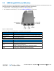
Figure 4-5. RAU Installed Above Acoustic Ceiling
3. Below/Mid-Mount Acoustic ceiling: Cut-out opening in acoustic tile (mid-mount only), install T-Bar in ceiling above, route
connections and install bracket on T-Bar.
NOTE: For Below ceiling installations - 22 mm (0.86 in) between ceiling tile and RAU; For Mid-Mount installations - 63.5 mm
(2.5 in) between ceiling and lowest part of RAU.
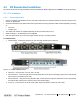
Figure 4-6. Below Ceiling Installation (left figure) and Mid-Mount Ceiling Installation (right image)
4. Connect cables: