
User's Manual


Installation – RF Path Elements
P/N 709C011801
Page 47
4.1.2 Example of HEU Master-Slave Installation
A Master-Slave HEU configuration enables single source management of several HEUs (and hosted elements) from a single HCM.
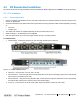
The following figure provides an example of the connections between a Master and one Slave.
Each OIU is connected to its host HEU through two connections: MGMT (ETH to INTERNAL port) and RF (RIX/OIX ports). For
standalone configurations, up to four OIU can be connected to an HEU; for Master/Slave configurations, up to three OIU can be
connected to an HEU (since one of the MGMT ports is used by the Master/Slave connections.)
Figure 4-2. Example of Connections for Master-Slave Configurations
4.1.3 OIU Installation
Note that each OIU interfaces to one HEU; each OIM interfaces to up to three RAU units (located at the remote end) via an MTP
connection.
To install OIU
1. Mount OIU - mount the (empty) OIU chassis in the 19-in rack.
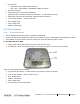
2. Install modules - install modules (OIM, OIX, PSM and ACM) into their respective slots. See following figure.
IMPORTANT! Unoccupied OIX (Expander Module) slots must be terminated with an Expander Termination module.
Figure 4-3. Fully Occupied OIU Chassis
3. Power-On - connect the Power Supply Module(s) to the AC outlet(s) and switch On. If two modules are installed, both
must be connected.
4. HEU connections:
o Connect the OIU OIX to the corresponding HEU RIX port using the provided Expander cable.
o Connect an ACM INTERNAL port to an HEU HCM INTERNAL port with an Ethernet cable.
5. OIM connections - connect the optic modules to the designated optic ports in the fiber-optic patch panel.
6. Verify OIU normal operation - via the LED indicators on the ACM and OIM modules. See sections ACM (Auxiliary
Control Module) (on page 34) and OIM (Optical Interface Module) (on page 35) respectively for description of
LEDs.