
User's Manual


Installation – RF Path Elements
P/N 709C011801
Page 45
4 Ins tallation – R F Path E lements
This chapter describes the installation of the RF path components. It contains only brief descriptions of the approach of each
installation procedure. For step-by-step installation descriptions, refer to the Quick Start Guides provided with the ordered units
and modules, and for specific guidelines on infrastructure planning, design and installation, please consult with a Corning
Product Line Manager or Corning approved Installer.
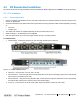
4.1 RF Headend Installation
The (RF coverage) headend site installation consists of installing the HEU and OIU units.
Note the following information (for both HEU and OIU units):
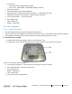
• The chassis and modules are supplied separately and must be inserted by the user. Only the fan module is factory installed
in the HEU/OIU chassis rear.
• The HEU and OIU units are installed at the IDF (Intermediate Distribution Frame), adjacent (or as close as possible) to each
other to facilitate the connections.
• Hot-swappable modules: RIM (RF Interface Modules) and Power Supply(ies), Fan Modules and RIX/OIX (HEU/OIU
Expander Modules). HCM, ACM modules are not hot-swappable.
• If a redundant power supply is provided, both supplies must be installed, connected to AC power and switched ON.
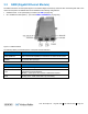
4.1.1 HEU Installation
Note the following information:
• The RF service interfaces are implemented by service specific RIM/RIM-M modules that are provided separately according to
your order.
• In a Master/Slave configuration, the HEU unit determined as the Slave is managed via the Master unit using an RJ45
connection. Also, the Slave HEU will include an ACM (Auxiliary Control Module) and not an HCM.