
User's Manual


Monitoring and Troubleshooting
P/N 709C011801
Page 124
9.2 Network Topology Tree - Fault Sourcing
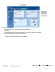
The Web GUI Management application Network Topology Tree is viewed in the Config main menu tab. The Network Topology
tree shows the elements of the HCM controller to which the session was opened, and the hosted devices. The connected network
devices are automatically detected in the baseline and displayed in the Network Topology Tree in the hierarchy in which they are
connected.
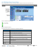
The Network Topology tree includes problem sourcing features such as:
• Color indication corresponding to the elements status
• Real-time updates of device status
• Upward propagated element status colors
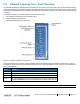
Figure 9-2. Example of Network Topology Tree
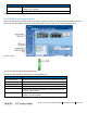
Each device element in the network topology is displayed along with adjacent LED corresponding to their status. Faults are
propagated only through an arrow so that the faulty device can be quickly identified by its color. The tree colors indicate the
status of the elements.
Color Indicates
Green OK
Yellow Minor Error
Red Major Error
Gray
No communication to a device set in Base-
Line. To remove from baseline, click
the Baseline Reset button in the System Management (HCM) Module Info tab.
Table 9-1. Tree Color Code Descriptions
NOTE: If communication to a device that was not set in Base-Line is lost, the device disappears from the display.