
User's Manual
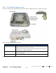


Table Of Contents
- Corning
- ONE™ Wireless Platform
- User Manual
- Preface Material
- About This Manual
- Hardware
- Software Warranty
- NOT LIMITED TO, INDIRECT, SPECIAL OR CONSEQUENTIAL DAMAGES ARISING OUT OF OR
- Returns
- Limitations of Liabilities
- Reporting Defects
- Warnings and Admonishments
- Regulatory Compliance Information
- RF Safety
- CAUTION!
- Laser Safety
- Licensee Contact Information
- Table of Contents
- 1 Introduction
- 1.1 About Corning ONE™
- 1.2 Key Features and Capabilities
- 1.3 General System Specifications and Requirements
- 1.4 Corning ONE™ WEB Management Application
- 1.5 User Controlled Service Group Distribution
- 2 Unit Descriptions - RF Path
- HEU hosts the following modules:
- 2.1.1.1 HCM (Headend Control Module)
- 2.1.1.2 ACM (Auxiliary Control Module)
- 2.1.1.3 RIM/RIM-M (RF Interface Module)
- 2.1.1.4 ETM (Expander Termination Module)
- 2.1.1.5 PSM (Power Supply Module)
- 2.1.1.6 PSM-AC (Power Supply Module-AC Power Source)
- 2.1.1.7 PSM-DC (Power Supply Module-DC Power Source)
- 2.1.2 OIU (Optical Interface Unit)
- OIU hosts the following modules:
- IHU hosts the following modules:
- 3 Unit Descriptions - Digital Path
- 4 Installation Guidelines
- 5 Installation – RF Path Elements
- 5.1 Headend Elements
- 5.1.1 HEU Installation
- 5.1.1.1 Unpacking and Inspection
- 5.1.1.2 Mounting the HEU Chassis
- 5.1.1.3 Installing all Modules
- 5.1.1.4 Grounding HEU Chassis
- 5.1.1.5 RIM Connections to RF Source
- 5.1.1.6 RIX to OIX Connections
- 5.1.1.7 Coax Connections for HEU-OIU 4X4 Installation Configurations
- 5.1.1.8 RIX Pilot Clock Connections
- 5.1.1.9 Management Connections
- 5.1.1.10 Power Up
- 5.1.1.11 Verify Normal operation
- 5.1.2 OIU Installation
- 5.1.3 HEU/OIU Cable Management Tray
- 5.1.1 HEU Installation
- 5.1 Headend Elements
- Note the following:
- 5.1.4 IHU Installation
- 5.1.4.1 Unpacking and Inspection
- 5.1.4.2 Assembling Cable Management Tray onto IHU and Connecting ERFC Cable
- 5.1.4.3 Mounting the IHU Chassis
- 5.1.4.4 Installing all Modules
- 5.1.4.5 Grounding IHU Chassis
- 5.1.4.6 IHU Expansion Connections to IHU, HEU and OIU Units
- 5.1.4.7 RIM Connections to RF Source
- 5.1.4.8 RIX 10 MHz Pilot Clock Connections
- 5.1.4.9 Management Connections
- 5.1.4.10 Power Up
- 5.1.4.11 Verify Normal operation
- 5.2 RF Remote-End Installation
- 5.2.1 ICU Installation
- 5.2.2 RAU Installation
- 5.2.2.1 General Information
- 5.2.2.2 Package Contents
- 5.2.2.3 Routing Connection Cables
- 5.2.2.4 Mounting RAU Installation Bracket (Wall/Concrete Ceiling)
- 5.2.2.5 Additional Bracket Installation Options
- 5.2.2.6 RAU Mid-Mount Installation Option
- 5.2.2.7 Connections
- 5.2.2.8 Mounting RAU onto Mounting Bracket
- 5.2.2.9 Verify RAU Modules Normal Operation
- 5.2.3 RAU5 Installation
- 5.2.3.1 General Information
- 5.2.3.2 Package Contents
- 5.2.3.3 Locate Required Connection Cables
- 5.2.3.4 Bracket Installation and Mounting RAU5
- 5.2.3.5 Cables Ground, F/O and RF connections
- 5.2.3.6 Main Power Connections
- 5.2.3.7 GEM Connections (for Configurations including GEM Modules)
- 5.2.3.8 Verify Normal Operation
- 5.2.4 RAU/RAU5/RxU Cavity Filter Installation
- 5.1.4 IHU Installation
- 6 Installation – Digital Coverage Elements
- 7 Appendix A: RAU Upgrades
- 8 Appendix B: RAU Mounting Bracket Installation Template Sheet (Scale 1:1)
- 9 Appendix C: RAU5 Bracket Dimensions
- 10 Appendix D: RAU5 Mid-Mount Bracket Assembly
- 11 Appendix E: Specifications
- Headend Unit (HEU) (continued)
- Optical Interface Unit (OIU) (continued)
- Digital Coverage Component Specifications
- 12 Appendix F: Ordering Information
- HEU and OIU Assemblies and Modules
- Remote Units
- Hardware
- Cable Ordering Information
- Cable Configurations

Installation Guidelines CMA-331-AEN Page 58
Draft
4 Installation Guidelines
The following installation assumes that site survey and installation planning (including power requirements) have been
completed. This includes planning the distribution of antennas to provide the required coverage, as well as planning the layout
of the devices and cables in the telecom closet or shaft.
4.1 Infrastructure Preparation
The following installation rules are based on the assumption that the site survey and installation planning (including power
requirements) have been completed.
4.2 Installation Requirements
The infrastructure preparation consists of two main phases:
A.
Floor Planning: Planning the distribution of the Remote Access Units (RAUs) on each floor to provide the required
coverage.
B.
Telecom Closet Planning: Planning the layout of the devices and cables in the telecom closet or shaft. This includes all
cabling and other voice service and digital coverage distribution systems that are relevant to the specific installation.
4.3 Safety Guidelines
Before installing the equipment review the following safety information:
• Follow all local safety regulations when installing the equipment.
• Only qualified personnel are authorized to install and maintain the Repeater.
• Ground specified equipment with the provided grounding bolt
• Do not use the grounding bolt to connect external devices.
• Follow Electro-Static Discharge (ESD) precautions.
• Use low loss cables to connect the antennas