
User's Manual

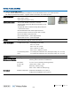


Table Of Contents
- Corning
- ONE™ Wireless Platform
- User Manual
- Preface Material
- About This Manual
- Hardware
- Software Warranty
- NOT LIMITED TO, INDIRECT, SPECIAL OR CONSEQUENTIAL DAMAGES ARISING OUT OF OR
- Returns
- Limitations of Liabilities
- Reporting Defects
- Warnings and Admonishments
- Regulatory Compliance Information
- RF Safety
- CAUTION!
- Laser Safety
- Licensee Contact Information
- Table of Contents
- 1 Introduction
- 1.1 About Corning ONE™
- 1.2 Key Features and Capabilities
- 1.3 General System Specifications and Requirements
- 1.4 Corning ONE™ WEB Management Application
- 1.5 User Controlled Service Group Distribution
- 2 Unit Descriptions - RF Path
- HEU hosts the following modules:
- 2.1.1.1 HCM (Headend Control Module)
- 2.1.1.2 ACM (Auxiliary Control Module)
- 2.1.1.3 RIM/RIM-M (RF Interface Module)
- 2.1.1.4 ETM (Expander Termination Module)
- 2.1.1.5 PSM (Power Supply Module)
- 2.1.1.6 PSM-AC (Power Supply Module-AC Power Source)
- 2.1.1.7 PSM-DC (Power Supply Module-DC Power Source)
- 2.1.2 OIU (Optical Interface Unit)
- OIU hosts the following modules:
- IHU hosts the following modules:
- 3 Unit Descriptions - Digital Path
- 4 Installation Guidelines
- 5 Installation – RF Path Elements
- 5.1 Headend Elements
- 5.1.1 HEU Installation
- 5.1.1.1 Unpacking and Inspection
- 5.1.1.2 Mounting the HEU Chassis
- 5.1.1.3 Installing all Modules
- 5.1.1.4 Grounding HEU Chassis
- 5.1.1.5 RIM Connections to RF Source
- 5.1.1.6 RIX to OIX Connections
- 5.1.1.7 Coax Connections for HEU-OIU 4X4 Installation Configurations
- 5.1.1.8 RIX Pilot Clock Connections
- 5.1.1.9 Management Connections
- 5.1.1.10 Power Up
- 5.1.1.11 Verify Normal operation
- 5.1.2 OIU Installation
- 5.1.3 HEU/OIU Cable Management Tray
- 5.1.1 HEU Installation
- 5.1 Headend Elements
- Note the following:
- 5.1.4 IHU Installation
- 5.1.4.1 Unpacking and Inspection
- 5.1.4.2 Assembling Cable Management Tray onto IHU and Connecting ERFC Cable
- 5.1.4.3 Mounting the IHU Chassis
- 5.1.4.4 Installing all Modules
- 5.1.4.5 Grounding IHU Chassis
- 5.1.4.6 IHU Expansion Connections to IHU, HEU and OIU Units
- 5.1.4.7 RIM Connections to RF Source
- 5.1.4.8 RIX 10 MHz Pilot Clock Connections
- 5.1.4.9 Management Connections
- 5.1.4.10 Power Up
- 5.1.4.11 Verify Normal operation
- 5.2 RF Remote-End Installation
- 5.2.1 ICU Installation
- 5.2.2 RAU Installation
- 5.2.2.1 General Information
- 5.2.2.2 Package Contents
- 5.2.2.3 Routing Connection Cables
- 5.2.2.4 Mounting RAU Installation Bracket (Wall/Concrete Ceiling)
- 5.2.2.5 Additional Bracket Installation Options
- 5.2.2.6 RAU Mid-Mount Installation Option
- 5.2.2.7 Connections
- 5.2.2.8 Mounting RAU onto Mounting Bracket
- 5.2.2.9 Verify RAU Modules Normal Operation
- 5.2.3 RAU5 Installation
- 5.2.3.1 General Information
- 5.2.3.2 Package Contents
- 5.2.3.3 Locate Required Connection Cables
- 5.2.3.4 Bracket Installation and Mounting RAU5
- 5.2.3.5 Cables Ground, F/O and RF connections
- 5.2.3.6 Main Power Connections
- 5.2.3.7 GEM Connections (for Configurations including GEM Modules)
- 5.2.3.8 Verify Normal Operation
- 5.2.4 RAU/RAU5/RxU Cavity Filter Installation
- 5.1.4 IHU Installation
- 6 Installation – Digital Coverage Elements
- 7 Appendix A: RAU Upgrades
- 8 Appendix B: RAU Mounting Bracket Installation Template Sheet (Scale 1:1)
- 9 Appendix C: RAU5 Bracket Dimensions
- 10 Appendix D: RAU5 Mid-Mount Bracket Assembly
- 11 Appendix E: Specifications
- Headend Unit (HEU) (continued)
- Optical Interface Unit (OIU) (continued)
- Digital Coverage Component Specifications
- 12 Appendix F: Ordering Information
- HEU and OIU Assemblies and Modules
- Remote Units
- Hardware
- Cable Ordering Information
- Cable Configurations

CMA-331-AEN Page 176
Draft
Remote Access Unit (RAU)
RAU will host the following modules:
1. RxU; Remote Expansion Module, for additional LTE and AWS MIMO service. One module per RAU5.
2. GEM; Giga bit Ethernet Module – upgrade module for the RAU5. One module per RAU5
Supported Services
SISO: CELL/ESMR, PCS, AWS, 700LTE
MIMO: AWS/ 700LTE
(with Expansion Module - RxU)
Interface Connections
Two LC APC SM fiber connectors; UL and DL
Two DC power Inputs ports; Main and secondary in case
of PoE clients.
Two QMA RF Ports; for External cavity filter (In/Out) use
- LTE and CELL filters
One Broadband External antenna QMA connector
(connected antenna must have a return loss of 12 dB)
One RJ-45 MGMT (local) connection
RxU module interface – power, digital and RF
GEM module Interface – power and digital
Antenna
Omni Directional; 0 dBi (15
◦
down from horizon)
Power Consumption
For Main Power Input: Input Range: 37-57 V DC
RAU: 44.5 V; 48 W
RAU + RxU: 44.5 V; 73 W
RAU + GEM: 44.5 V; 52 W
RAU + RxU + GEM: 44.5 V; 77 W
For Secondary Power
Input:
For 2 PoE ports of 802.3af: 46 V; 31.5 W (Input range: 43 - 57 V DC)
For 2 PoE ports of 802.3at: 52.5 V; 62 W (Input range: 52 - 57 V DC)
Management
Managed via the HCM
Physical Characteristics
(Enclosure and Modules)
Mounting: Wall/ceiling (Horizontal mount)
Mounting bracket included in installation kit
Mid-mount (acoustic ceiling) – separately ordered kit
Dimensions
(H x W X D):
Without mounting bracket: 3.2 x 12.9 x 9.8 in (82.1 x 337.3 x 249.4 mm)
With mounting bracket: 5.25 x 13.1 x 13.1 in (133.35 x 332.74 x 332.74
mm)
Weight: R RAU5 only: 10 lbs (4.5 kg)
RAU5 and RXU and GEM: 14.39 lbs (6.5 kg)
Environment
Ambient Temperature:
Wall-mount installations: 45
◦
C (113
◦
F)
Ceiling-mount installations: 50
◦
C (122
◦
F)