
User's Manual


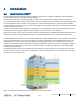

Table Of Contents
- Corning
- ONE™ Wireless Platform
- User Manual
- Preface Material
- About This Manual
- Hardware
- Software Warranty
- NOT LIMITED TO, INDIRECT, SPECIAL OR CONSEQUENTIAL DAMAGES ARISING OUT OF OR
- Returns
- Limitations of Liabilities
- Reporting Defects
- Warnings and Admonishments
- Regulatory Compliance Information
- RF Safety
- CAUTION!
- Laser Safety
- Licensee Contact Information
- Table of Contents
- 1 Introduction
- 1.1 About Corning ONE™
- 1.2 Key Features and Capabilities
- 1.3 General System Specifications and Requirements
- 1.4 Corning ONE™ WEB Management Application
- 1.5 User Controlled Service Group Distribution
- 2 Unit Descriptions - RF Path
- HEU hosts the following modules:
- 2.1.1.1 HCM (Headend Control Module)
- 2.1.1.2 ACM (Auxiliary Control Module)
- 2.1.1.3 RIM/RIM-M (RF Interface Module)
- 2.1.1.4 ETM (Expander Termination Module)
- 2.1.1.5 PSM (Power Supply Module)
- 2.1.1.6 PSM-AC (Power Supply Module-AC Power Source)
- 2.1.1.7 PSM-DC (Power Supply Module-DC Power Source)
- 2.1.2 OIU (Optical Interface Unit)
- OIU hosts the following modules:
- IHU hosts the following modules:
- 3 Unit Descriptions - Digital Path
- 4 Installation Guidelines
- 5 Installation – RF Path Elements
- 5.1 Headend Elements
- 5.1.1 HEU Installation
- 5.1.1.1 Unpacking and Inspection
- 5.1.1.2 Mounting the HEU Chassis
- 5.1.1.3 Installing all Modules
- 5.1.1.4 Grounding HEU Chassis
- 5.1.1.5 RIM Connections to RF Source
- 5.1.1.6 RIX to OIX Connections
- 5.1.1.7 Coax Connections for HEU-OIU 4X4 Installation Configurations
- 5.1.1.8 RIX Pilot Clock Connections
- 5.1.1.9 Management Connections
- 5.1.1.10 Power Up
- 5.1.1.11 Verify Normal operation
- 5.1.2 OIU Installation
- 5.1.3 HEU/OIU Cable Management Tray
- 5.1.1 HEU Installation
- 5.1 Headend Elements
- Note the following:
- 5.1.4 IHU Installation
- 5.1.4.1 Unpacking and Inspection
- 5.1.4.2 Assembling Cable Management Tray onto IHU and Connecting ERFC Cable
- 5.1.4.3 Mounting the IHU Chassis
- 5.1.4.4 Installing all Modules
- 5.1.4.5 Grounding IHU Chassis
- 5.1.4.6 IHU Expansion Connections to IHU, HEU and OIU Units
- 5.1.4.7 RIM Connections to RF Source
- 5.1.4.8 RIX 10 MHz Pilot Clock Connections
- 5.1.4.9 Management Connections
- 5.1.4.10 Power Up
- 5.1.4.11 Verify Normal operation
- 5.2 RF Remote-End Installation
- 5.2.1 ICU Installation
- 5.2.2 RAU Installation
- 5.2.2.1 General Information
- 5.2.2.2 Package Contents
- 5.2.2.3 Routing Connection Cables
- 5.2.2.4 Mounting RAU Installation Bracket (Wall/Concrete Ceiling)
- 5.2.2.5 Additional Bracket Installation Options
- 5.2.2.6 RAU Mid-Mount Installation Option
- 5.2.2.7 Connections
- 5.2.2.8 Mounting RAU onto Mounting Bracket
- 5.2.2.9 Verify RAU Modules Normal Operation
- 5.2.3 RAU5 Installation
- 5.2.3.1 General Information
- 5.2.3.2 Package Contents
- 5.2.3.3 Locate Required Connection Cables
- 5.2.3.4 Bracket Installation and Mounting RAU5
- 5.2.3.5 Cables Ground, F/O and RF connections
- 5.2.3.6 Main Power Connections
- 5.2.3.7 GEM Connections (for Configurations including GEM Modules)
- 5.2.3.8 Verify Normal Operation
- 5.2.4 RAU/RAU5/RxU Cavity Filter Installation
- 5.1.4 IHU Installation
- 6 Installation – Digital Coverage Elements
- 7 Appendix A: RAU Upgrades
- 8 Appendix B: RAU Mounting Bracket Installation Template Sheet (Scale 1:1)
- 9 Appendix C: RAU5 Bracket Dimensions
- 10 Appendix D: RAU5 Mid-Mount Bracket Assembly
- 11 Appendix E: Specifications
- Headend Unit (HEU) (continued)
- Optical Interface Unit (OIU) (continued)
- Digital Coverage Component Specifications
- 12 Appendix F: Ordering Information
- HEU and OIU Assemblies and Modules
- Remote Units
- Hardware
- Cable Ordering Information
- Cable Configurations

Introduction P/N 709C011801 Page 15
Draft
1 Introduction
1.1 About Corning ONE™
The Corning Optical Network Evolution Platform (ONE) by Corning provides a flexible in-building RF and network digital
coverage solution based on a fiber optic transport backbone.
The fiber-optics infrastructure is easily deployable via a wide range of pre-terminated composite cables and advanced
end-to-end equipment. Easy to design, Plug and Play™ connectors, significantly reduce installation cost and deployment time.
The Corning ONE solution is an ideal fit for large, high-rise or campus-style deployments. It generates significant CAPEX
savings and OPEX savings through the use of user configurable service distribution groups and an infrastructure that is simple
to deploy and efficient in usage.
Dynamic service distribution group management allows precise service distribution control to meet changing density needs,
and provides further savings by enabling sharing of equipment at various levels for service providers.
Radio source agnostic, remote units can be used as network extenders. Ethernet capability with dedicated fiber link for Wi-Fi
offload brings a higher level of granularity and support for devices and applications with very high speed requirements.
Corning ONE fiber-optics infrastructure allows various combinations of SISO and MIMO services to be routed from the headend
to specified remote locations on each floor, according to user defined configurations (via the Web Management GUI). This
allows optimizing service coverage and provides equipment savings. While the fiber-optics infrastructure is common, the
services can be routed via service provider shared or dedicated equipment. By default, the system is configured to support a
single service group: all services are transferred to all remote locations. This default configuration can be easily modified
according to site requirements.
The following figure illustrates service distribution from the head-end to various locations on each remote floor. Each color
represents a specific service, where different combinations of services are distributed at various locations on the same floor
according to coverage requirements.
Figure 1-1. Illustration of Precise Service Distribution over Selected Remote Areas