
User's Manual
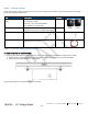

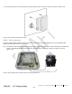
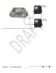
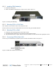
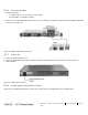
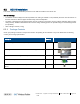
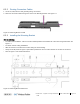
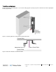
Table Of Contents
- Corning
- ONE™ Wireless Platform
- User Manual
- Preface Material
- About This Manual
- Hardware
- Software Warranty
- NOT LIMITED TO, INDIRECT, SPECIAL OR CONSEQUENTIAL DAMAGES ARISING OUT OF OR
- Returns
- Limitations of Liabilities
- Reporting Defects
- Warnings and Admonishments
- Regulatory Compliance Information
- RF Safety
- CAUTION!
- Laser Safety
- Licensee Contact Information
- Table of Contents
- 1 Introduction
- 1.1 About Corning ONE™
- 1.2 Key Features and Capabilities
- 1.3 General System Specifications and Requirements
- 1.4 Corning ONE™ WEB Management Application
- 1.5 User Controlled Service Group Distribution
- 2 Unit Descriptions - RF Path
- HEU hosts the following modules:
- 2.1.1.1 HCM (Headend Control Module)
- 2.1.1.2 ACM (Auxiliary Control Module)
- 2.1.1.3 RIM/RIM-M (RF Interface Module)
- 2.1.1.4 ETM (Expander Termination Module)
- 2.1.1.5 PSM (Power Supply Module)
- 2.1.1.6 PSM-AC (Power Supply Module-AC Power Source)
- 2.1.1.7 PSM-DC (Power Supply Module-DC Power Source)
- 2.1.2 OIU (Optical Interface Unit)
- OIU hosts the following modules:
- IHU hosts the following modules:
- 3 Unit Descriptions - Digital Path
- 4 Installation Guidelines
- 5 Installation – RF Path Elements
- 5.1 Headend Elements
- 5.1.1 HEU Installation
- 5.1.1.1 Unpacking and Inspection
- 5.1.1.2 Mounting the HEU Chassis
- 5.1.1.3 Installing all Modules
- 5.1.1.4 Grounding HEU Chassis
- 5.1.1.5 RIM Connections to RF Source
- 5.1.1.6 RIX to OIX Connections
- 5.1.1.7 Coax Connections for HEU-OIU 4X4 Installation Configurations
- 5.1.1.8 RIX Pilot Clock Connections
- 5.1.1.9 Management Connections
- 5.1.1.10 Power Up
- 5.1.1.11 Verify Normal operation
- 5.1.2 OIU Installation
- 5.1.3 HEU/OIU Cable Management Tray
- 5.1.1 HEU Installation
- 5.1 Headend Elements
- Note the following:
- 5.1.4 IHU Installation
- 5.1.4.1 Unpacking and Inspection
- 5.1.4.2 Assembling Cable Management Tray onto IHU and Connecting ERFC Cable
- 5.1.4.3 Mounting the IHU Chassis
- 5.1.4.4 Installing all Modules
- 5.1.4.5 Grounding IHU Chassis
- 5.1.4.6 IHU Expansion Connections to IHU, HEU and OIU Units
- 5.1.4.7 RIM Connections to RF Source
- 5.1.4.8 RIX 10 MHz Pilot Clock Connections
- 5.1.4.9 Management Connections
- 5.1.4.10 Power Up
- 5.1.4.11 Verify Normal operation
- 5.2 RF Remote-End Installation
- 5.2.1 ICU Installation
- 5.2.2 RAU Installation
- 5.2.2.1 General Information
- 5.2.2.2 Package Contents
- 5.2.2.3 Routing Connection Cables
- 5.2.2.4 Mounting RAU Installation Bracket (Wall/Concrete Ceiling)
- 5.2.2.5 Additional Bracket Installation Options
- 5.2.2.6 RAU Mid-Mount Installation Option
- 5.2.2.7 Connections
- 5.2.2.8 Mounting RAU onto Mounting Bracket
- 5.2.2.9 Verify RAU Modules Normal Operation
- 5.2.3 RAU5 Installation
- 5.2.3.1 General Information
- 5.2.3.2 Package Contents
- 5.2.3.3 Locate Required Connection Cables
- 5.2.3.4 Bracket Installation and Mounting RAU5
- 5.2.3.5 Cables Ground, F/O and RF connections
- 5.2.3.6 Main Power Connections
- 5.2.3.7 GEM Connections (for Configurations including GEM Modules)
- 5.2.3.8 Verify Normal Operation
- 5.2.4 RAU/RAU5/RxU Cavity Filter Installation
- 5.1.4 IHU Installation
- 6 Installation – Digital Coverage Elements
- 7 Appendix A: RAU Upgrades
- 8 Appendix B: RAU Mounting Bracket Installation Template Sheet (Scale 1:1)
- 9 Appendix C: RAU5 Bracket Dimensions
- 10 Appendix D: RAU5 Mid-Mount Bracket Assembly
- 11 Appendix E: Specifications
- Headend Unit (HEU) (continued)
- Optical Interface Unit (OIU) (continued)
- Digital Coverage Component Specifications
- 12 Appendix F: Ordering Information
- HEU and OIU Assemblies and Modules
- Remote Units
- Hardware
- Cable Ordering Information
- Cable Configurations

Installation – Digital Coverage Elements P/N 709C011801 Page 145
Draft
6 Installation – Digital Coverage Elements
This chapter describes the installation procedures for each of the Digital Coverage components. It contains only brief
descriptions of the approach of each installation procedure. For specific guidelines on infrastructure planning, design and
installation, please consult with a Corning Product Line Manager or Corning approved Installer. All these elements are installed
at the remote end.
6.1 CEU Installation
General Information
• The CEU interfaces to the main Ethernet switch and to the remote Gigabit Ethernet Modules (GEM).
• The CEU is rack mounted or wall mounted at the IDF (Intermediate Distribution Frame).
• The CEU can host up to three Centralized Ethernet Modules (CEMs), which are not included in the CEU package (ordered
separately).
• The CEM Tx/Rx Ethernet fiber ports, used for interfacing to the GEM modules, require SFP modules (included) and LC-UPC
to LC APC adapter if using LC/APC fiber.
6.1.1 Items Required for CEU Installation
The following items are required for installing the ONE™ CEU. If any of the listed items are missing, contact your Corning
representative.
CEU KIT
Quantity
Central Ethernet Unit (CEU) with power supply 1
Standard IEC right angle 110-240VAC, 50-60 Hz cable 1
Wall mount brackets 2
CEM KIT
Quantity
Central Ethernet Module (CEM) 1
SFP modules (pre-inserted in Tx/Rx ports) 4
ATT. LC/HAP 0dB – used for APC cable 8
Table 6-1. Items Required for CEU Installation