
User's Manual

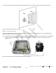
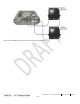
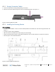
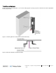
Table Of Contents
- Corning
- ONE™ Wireless Platform
- User Manual
- Preface Material
- About This Manual
- Hardware
- Software Warranty
- NOT LIMITED TO, INDIRECT, SPECIAL OR CONSEQUENTIAL DAMAGES ARISING OUT OF OR
- Returns
- Limitations of Liabilities
- Reporting Defects
- Warnings and Admonishments
- Regulatory Compliance Information
- RF Safety
- CAUTION!
- Laser Safety
- Licensee Contact Information
- Table of Contents
- 1 Introduction
- 1.1 About Corning ONE™
- 1.2 Key Features and Capabilities
- 1.3 General System Specifications and Requirements
- 1.4 Corning ONE™ WEB Management Application
- 1.5 User Controlled Service Group Distribution
- 2 Unit Descriptions - RF Path
- HEU hosts the following modules:
- 2.1.1.1 HCM (Headend Control Module)
- 2.1.1.2 ACM (Auxiliary Control Module)
- 2.1.1.3 RIM/RIM-M (RF Interface Module)
- 2.1.1.4 ETM (Expander Termination Module)
- 2.1.1.5 PSM (Power Supply Module)
- 2.1.1.6 PSM-AC (Power Supply Module-AC Power Source)
- 2.1.1.7 PSM-DC (Power Supply Module-DC Power Source)
- 2.1.2 OIU (Optical Interface Unit)
- OIU hosts the following modules:
- IHU hosts the following modules:
- 3 Unit Descriptions - Digital Path
- 4 Installation Guidelines
- 5 Installation – RF Path Elements
- 5.1 Headend Elements
- 5.1.1 HEU Installation
- 5.1.1.1 Unpacking and Inspection
- 5.1.1.2 Mounting the HEU Chassis
- 5.1.1.3 Installing all Modules
- 5.1.1.4 Grounding HEU Chassis
- 5.1.1.5 RIM Connections to RF Source
- 5.1.1.6 RIX to OIX Connections
- 5.1.1.7 Coax Connections for HEU-OIU 4X4 Installation Configurations
- 5.1.1.8 RIX Pilot Clock Connections
- 5.1.1.9 Management Connections
- 5.1.1.10 Power Up
- 5.1.1.11 Verify Normal operation
- 5.1.2 OIU Installation
- 5.1.3 HEU/OIU Cable Management Tray
- 5.1.1 HEU Installation
- 5.1 Headend Elements
- Note the following:
- 5.1.4 IHU Installation
- 5.1.4.1 Unpacking and Inspection
- 5.1.4.2 Assembling Cable Management Tray onto IHU and Connecting ERFC Cable
- 5.1.4.3 Mounting the IHU Chassis
- 5.1.4.4 Installing all Modules
- 5.1.4.5 Grounding IHU Chassis
- 5.1.4.6 IHU Expansion Connections to IHU, HEU and OIU Units
- 5.1.4.7 RIM Connections to RF Source
- 5.1.4.8 RIX 10 MHz Pilot Clock Connections
- 5.1.4.9 Management Connections
- 5.1.4.10 Power Up
- 5.1.4.11 Verify Normal operation
- 5.2 RF Remote-End Installation
- 5.2.1 ICU Installation
- 5.2.2 RAU Installation
- 5.2.2.1 General Information
- 5.2.2.2 Package Contents
- 5.2.2.3 Routing Connection Cables
- 5.2.2.4 Mounting RAU Installation Bracket (Wall/Concrete Ceiling)
- 5.2.2.5 Additional Bracket Installation Options
- 5.2.2.6 RAU Mid-Mount Installation Option
- 5.2.2.7 Connections
- 5.2.2.8 Mounting RAU onto Mounting Bracket
- 5.2.2.9 Verify RAU Modules Normal Operation
- 5.2.3 RAU5 Installation
- 5.2.3.1 General Information
- 5.2.3.2 Package Contents
- 5.2.3.3 Locate Required Connection Cables
- 5.2.3.4 Bracket Installation and Mounting RAU5
- 5.2.3.5 Cables Ground, F/O and RF connections
- 5.2.3.6 Main Power Connections
- 5.2.3.7 GEM Connections (for Configurations including GEM Modules)
- 5.2.3.8 Verify Normal Operation
- 5.2.4 RAU/RAU5/RxU Cavity Filter Installation
- 5.1.4 IHU Installation
- 6 Installation – Digital Coverage Elements
- 7 Appendix A: RAU Upgrades
- 8 Appendix B: RAU Mounting Bracket Installation Template Sheet (Scale 1:1)
- 9 Appendix C: RAU5 Bracket Dimensions
- 10 Appendix D: RAU5 Mid-Mount Bracket Assembly
- 11 Appendix E: Specifications
- Headend Unit (HEU) (continued)
- Optical Interface Unit (OIU) (continued)
- Digital Coverage Component Specifications
- 12 Appendix F: Ordering Information
- HEU and OIU Assemblies and Modules
- Remote Units
- Hardware
- Cable Ordering Information
- Cable Configurations

Installation – RF Path Elements CMA-331-AEN Page 142
Draft
5.2.4.3 Acoustic Ceiling Mount Installation
In acoustic ceiling mount installations, the Cavity Filter can be fastened to the grid by slipping tie wraps through slits on the
bracket (Item C in Figure 5-97) and securing the assembly to the grid with the provided safety cable. Refer to Figure 5-99.
Figure 5-99. Illustration of Cavity Filter Mounted on Acoustic Ceiling Grid
5.2.4.4 Wall Mount Installation
To mount Cavity Filter on Wall
1. Using the four key holes (Item A in Figure 5-97) as a guide, mark the location of the holes to be drilled in the wall.
2. Drill the holes in the wall corresponding to the diameter of the anchors to be used (not provided).
Figure 5-100. Marking and Inserting Anchors in Wall