
User's Manual
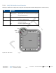
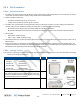
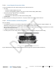
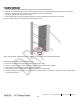


Table Of Contents
- Corning
- ONE™ Wireless Platform
- User Manual
- Preface Material
- About This Manual
- Hardware
- Software Warranty
- NOT LIMITED TO, INDIRECT, SPECIAL OR CONSEQUENTIAL DAMAGES ARISING OUT OF OR
- Returns
- Limitations of Liabilities
- Reporting Defects
- Warnings and Admonishments
- Regulatory Compliance Information
- RF Safety
- CAUTION!
- Laser Safety
- Licensee Contact Information
- Table of Contents
- 1 Introduction
- 1.1 About Corning ONE™
- 1.2 Key Features and Capabilities
- 1.3 General System Specifications and Requirements
- 1.4 Corning ONE™ WEB Management Application
- 1.5 User Controlled Service Group Distribution
- 2 Unit Descriptions - RF Path
- HEU hosts the following modules:
- 2.1.1.1 HCM (Headend Control Module)
- 2.1.1.2 ACM (Auxiliary Control Module)
- 2.1.1.3 RIM/RIM-M (RF Interface Module)
- 2.1.1.4 ETM (Expander Termination Module)
- 2.1.1.5 PSM (Power Supply Module)
- 2.1.1.6 PSM-AC (Power Supply Module-AC Power Source)
- 2.1.1.7 PSM-DC (Power Supply Module-DC Power Source)
- 2.1.2 OIU (Optical Interface Unit)
- OIU hosts the following modules:
- IHU hosts the following modules:
- 3 Unit Descriptions - Digital Path
- 4 Installation Guidelines
- 5 Installation – RF Path Elements
- 5.1 Headend Elements
- 5.1.1 HEU Installation
- 5.1.1.1 Unpacking and Inspection
- 5.1.1.2 Mounting the HEU Chassis
- 5.1.1.3 Installing all Modules
- 5.1.1.4 Grounding HEU Chassis
- 5.1.1.5 RIM Connections to RF Source
- 5.1.1.6 RIX to OIX Connections
- 5.1.1.7 Coax Connections for HEU-OIU 4X4 Installation Configurations
- 5.1.1.8 RIX Pilot Clock Connections
- 5.1.1.9 Management Connections
- 5.1.1.10 Power Up
- 5.1.1.11 Verify Normal operation
- 5.1.2 OIU Installation
- 5.1.3 HEU/OIU Cable Management Tray
- 5.1.1 HEU Installation
- 5.1 Headend Elements
- Note the following:
- 5.1.4 IHU Installation
- 5.1.4.1 Unpacking and Inspection
- 5.1.4.2 Assembling Cable Management Tray onto IHU and Connecting ERFC Cable
- 5.1.4.3 Mounting the IHU Chassis
- 5.1.4.4 Installing all Modules
- 5.1.4.5 Grounding IHU Chassis
- 5.1.4.6 IHU Expansion Connections to IHU, HEU and OIU Units
- 5.1.4.7 RIM Connections to RF Source
- 5.1.4.8 RIX 10 MHz Pilot Clock Connections
- 5.1.4.9 Management Connections
- 5.1.4.10 Power Up
- 5.1.4.11 Verify Normal operation
- 5.2 RF Remote-End Installation
- 5.2.1 ICU Installation
- 5.2.2 RAU Installation
- 5.2.2.1 General Information
- 5.2.2.2 Package Contents
- 5.2.2.3 Routing Connection Cables
- 5.2.2.4 Mounting RAU Installation Bracket (Wall/Concrete Ceiling)
- 5.2.2.5 Additional Bracket Installation Options
- 5.2.2.6 RAU Mid-Mount Installation Option
- 5.2.2.7 Connections
- 5.2.2.8 Mounting RAU onto Mounting Bracket
- 5.2.2.9 Verify RAU Modules Normal Operation
- 5.2.3 RAU5 Installation
- 5.2.3.1 General Information
- 5.2.3.2 Package Contents
- 5.2.3.3 Locate Required Connection Cables
- 5.2.3.4 Bracket Installation and Mounting RAU5
- 5.2.3.5 Cables Ground, F/O and RF connections
- 5.2.3.6 Main Power Connections
- 5.2.3.7 GEM Connections (for Configurations including GEM Modules)
- 5.2.3.8 Verify Normal Operation
- 5.2.4 RAU/RAU5/RxU Cavity Filter Installation
- 5.1.4 IHU Installation
- 6 Installation – Digital Coverage Elements
- 7 Appendix A: RAU Upgrades
- 8 Appendix B: RAU Mounting Bracket Installation Template Sheet (Scale 1:1)
- 9 Appendix C: RAU5 Bracket Dimensions
- 10 Appendix D: RAU5 Mid-Mount Bracket Assembly
- 11 Appendix E: Specifications
- Headend Unit (HEU) (continued)
- Optical Interface Unit (OIU) (continued)
- Digital Coverage Component Specifications
- 12 Appendix F: Ordering Information
- HEU and OIU Assemblies and Modules
- Remote Units
- Hardware
- Cable Ordering Information
- Cable Configurations

Installation – RF Path Elements CMA-331-AEN Page 140
Draft
5.2.4 RAU/RAU5/RxU Cavity Filter Installation
The external cavity filters are required when the RF services modules supporting the corresponding CELL and LTE bands are
deployed alongside units supporting the public safety service.
• The RAU/RAU5 supports connections to External CELL and LTE Filters
• The RxU supports connections to an External LTE Filter.
• In cases where an LTE External Filter is required and the RAU/RAU5 includes the RxU module – both modules must be
connected to an external LTE filter.
Note the following:
• The Cavity Filter mounting bracket supports wall/ceiling/acoustic ceiling installations. See Figure 5-97.
Figure 5-97.Cavity Filter Dimensions and Mounting Holes
• Consider the length of the RF jumpers (3m) and the distance from the RAU when determining the installation location.
• For acoustic ceiling installations – use provided safety cable to secure the filter assembly to a permanent structure within the
ceiling (e.g. acoustic ceiling grid or concrete ceiling above).