
User's Manual
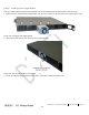
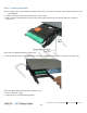


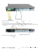
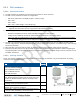

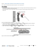
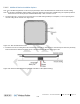
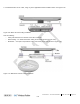
Table Of Contents
- Corning
- ONE™ Wireless Platform
- User Manual
- Preface Material
- About This Manual
- Hardware
- Software Warranty
- NOT LIMITED TO, INDIRECT, SPECIAL OR CONSEQUENTIAL DAMAGES ARISING OUT OF OR
- Returns
- Limitations of Liabilities
- Reporting Defects
- Warnings and Admonishments
- Regulatory Compliance Information
- RF Safety
- CAUTION!
- Laser Safety
- Licensee Contact Information
- Table of Contents
- 1 Introduction
- 1.1 About Corning ONE™
- 1.2 Key Features and Capabilities
- 1.3 General System Specifications and Requirements
- 1.4 Corning ONE™ WEB Management Application
- 1.5 User Controlled Service Group Distribution
- 2 Unit Descriptions - RF Path
- HEU hosts the following modules:
- 2.1.1.1 HCM (Headend Control Module)
- 2.1.1.2 ACM (Auxiliary Control Module)
- 2.1.1.3 RIM/RIM-M (RF Interface Module)
- 2.1.1.4 ETM (Expander Termination Module)
- 2.1.1.5 PSM (Power Supply Module)
- 2.1.1.6 PSM-AC (Power Supply Module-AC Power Source)
- 2.1.1.7 PSM-DC (Power Supply Module-DC Power Source)
- 2.1.2 OIU (Optical Interface Unit)
- OIU hosts the following modules:
- IHU hosts the following modules:
- 3 Unit Descriptions - Digital Path
- 4 Installation Guidelines
- 5 Installation – RF Path Elements
- 5.1 Headend Elements
- 5.1.1 HEU Installation
- 5.1.1.1 Unpacking and Inspection
- 5.1.1.2 Mounting the HEU Chassis
- 5.1.1.3 Installing all Modules
- 5.1.1.4 Grounding HEU Chassis
- 5.1.1.5 RIM Connections to RF Source
- 5.1.1.6 RIX to OIX Connections
- 5.1.1.7 Coax Connections for HEU-OIU 4X4 Installation Configurations
- 5.1.1.8 RIX Pilot Clock Connections
- 5.1.1.9 Management Connections
- 5.1.1.10 Power Up
- 5.1.1.11 Verify Normal operation
- 5.1.2 OIU Installation
- 5.1.3 HEU/OIU Cable Management Tray
- 5.1.1 HEU Installation
- 5.1 Headend Elements
- Note the following:
- 5.1.4 IHU Installation
- 5.1.4.1 Unpacking and Inspection
- 5.1.4.2 Assembling Cable Management Tray onto IHU and Connecting ERFC Cable
- 5.1.4.3 Mounting the IHU Chassis
- 5.1.4.4 Installing all Modules
- 5.1.4.5 Grounding IHU Chassis
- 5.1.4.6 IHU Expansion Connections to IHU, HEU and OIU Units
- 5.1.4.7 RIM Connections to RF Source
- 5.1.4.8 RIX 10 MHz Pilot Clock Connections
- 5.1.4.9 Management Connections
- 5.1.4.10 Power Up
- 5.1.4.11 Verify Normal operation
- 5.2 RF Remote-End Installation
- 5.2.1 ICU Installation
- 5.2.2 RAU Installation
- 5.2.2.1 General Information
- 5.2.2.2 Package Contents
- 5.2.2.3 Routing Connection Cables
- 5.2.2.4 Mounting RAU Installation Bracket (Wall/Concrete Ceiling)
- 5.2.2.5 Additional Bracket Installation Options
- 5.2.2.6 RAU Mid-Mount Installation Option
- 5.2.2.7 Connections
- 5.2.2.8 Mounting RAU onto Mounting Bracket
- 5.2.2.9 Verify RAU Modules Normal Operation
- 5.2.3 RAU5 Installation
- 5.2.3.1 General Information
- 5.2.3.2 Package Contents
- 5.2.3.3 Locate Required Connection Cables
- 5.2.3.4 Bracket Installation and Mounting RAU5
- 5.2.3.5 Cables Ground, F/O and RF connections
- 5.2.3.6 Main Power Connections
- 5.2.3.7 GEM Connections (for Configurations including GEM Modules)
- 5.2.3.8 Verify Normal Operation
- 5.2.4 RAU/RAU5/RxU Cavity Filter Installation
- 5.1.4 IHU Installation
- 6 Installation – Digital Coverage Elements
- 7 Appendix A: RAU Upgrades
- 8 Appendix B: RAU Mounting Bracket Installation Template Sheet (Scale 1:1)
- 9 Appendix C: RAU5 Bracket Dimensions
- 10 Appendix D: RAU5 Mid-Mount Bracket Assembly
- 11 Appendix E: Specifications
- Headend Unit (HEU) (continued)
- Optical Interface Unit (OIU) (continued)
- Digital Coverage Component Specifications
- 12 Appendix F: Ordering Information
- HEU and OIU Assemblies and Modules
- Remote Units
- Hardware
- Cable Ordering Information
- Cable Configurations

Installation – RF Path Elements CMA-331-AEN Page 116
Draft
5.2.2 RAU Installation
5.2.2.1 General Information
1. The RAU modules are deployed on the floor level and interface to the RF antennas.
2. The RAU can be provided in a number of configurations:
• RAU alone (without RxU and GEM); weight = 7.93 lbs (3.6 kg)
• RAU + RxU
• RAU + GEM
• RAU + RxU + GEM; weight = 12.12 lbs (5.5 kg)
Note: Existing RAU units can be upgraded with RxU (for MIMO support) and/or GEM modules (for Ethernet services) – see
Appendix A for instructions on how to upgrade the RAU with these modules.
3. The RAU supports various mounting installation options:
• Wall-mount installations (vertical); required ambient temperature of 45
◦
C [113
◦
F]
• Ceiling-mount installations (horizontal): required ambient temperature of 45
◦
C 50
◦
C [122
◦
F]
Note: If the RAU is installed below or mid-mount an acoustic ceiling, a support bar (T-Bar) is required (not included).
Acoustical ceiling grid work is not designed to support the weight of the enclosure.
4. The RAU unit is provided with a mounting bracket used for mounting on the wall or concrete ceilings (including above
acoustic ceiling mounts). Additional below/mid-mount acoustic ceiling mounting options are possible using a T-Bar mounting
bracket (not provided).
5. RAU optic fiber connections and DC power are provided via a Corning Composite cable (ordered separately).
6. External cavity filters (AK-CVT700; AK-CVT800) are required for installations in which RAU/RXU modules supporting the
corresponding CELL and LTE bands are deployed alongside units supporting the public safety service. See section 5.2.3 for
installation instructions.
5.2.2.2 Package Contents
Check your package contents to verify that the items in the packing list are included. If any of the listed items are missing,
contact your Corning representative.
Item
Quantity
Image
Remote Access Unit (RAU):
RAU-R-G-C85P19L70A17-ME
RAU-R-C85P19L70A17-M
RAU-G-C85P19L70A17-E
RAU-C85P19L70A17
1
Mounting Bracket (factory assembled on RAU underside)
Note: Mounting Bracket includes holes in various sizes and
locations for flexible installation options. Mounting screws
not provided.
1
Screw, SEM 8-32X3/8 , Pan Head, Philips - used for
grounding and to secure bracket to RAU
2
“Skirt” Frame Cover – used for acoustic ceiling cut-out
template and for aesthetic installation
1
Safety Cable – used to secure RAU to permanent structure
in acoustic ceiling installations; connected to RAU
1