
User's Manual

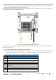

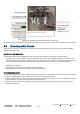


Table Of Contents
- Corning
- Mid-Power Remote Unit (MRU)
- Preface Material
- About This Manual
- Hardware
- Software Warranty
- Returns
- Limitations of Liabilities
- Reporting Defects
- Warnings and Admonishments
- Regulatory Compliance Information
- RF Safety
- Laser Safety
- Care of Fiber Optic Connectors
- Company Certification
- Licensee Contact Information
- Table of Contents
- 1 Introduction
- 2 MRU Interfaces
- 3 Installation Guidelines
- 4 Installation
- 5 Appendix A: Specifications
- Supported Services
- Coupling Specifications
- Physical Specifications
- 6 Appendix B: Ordering Information

Installation CMA-XXX-AEN Page 40
Draft
4.7.2.2 CLASS1 Connector (Local Plant Feed)
Note: In order to power the MRU via the CLASS1 connector (2 pole terminal plug), the DC bridge must be moved from the
default CLASS2 mode position to CLASS1.
DC CLASS1 power specs:
• Power input: 48 VDC (40-60VDC)
• Max. current consumption: 9 A
To perform CLASS1 DC connector wiring
1. Loosen PEM captive screws and pull out module from chassis. See Figure 4-22.
Figure 4-22. Extracting PEM from Chassis
2. Move DC bridge from CLASS2 position to CLASS1 to set DC input source type to ‘CLASS1’ connector. Refer to
Figure 4-23.
Figure 4-23. Setting CLASS1 Mode