
User's Manual

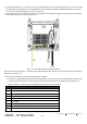


Table Of Contents
- Corning
- Mid-Power Remote Unit (MRU)
- Preface Material
- About This Manual
- Hardware
- Software Warranty
- Returns
- Limitations of Liabilities
- Reporting Defects
- Warnings and Admonishments
- Regulatory Compliance Information
- RF Safety
- Laser Safety
- Care of Fiber Optic Connectors
- Company Certification
- Licensee Contact Information
- Table of Contents
- 1 Introduction
- 2 MRU Interfaces
- 3 Installation Guidelines
- 4 Installation
- 5 Appendix A: Specifications
- Supported Services
- Coupling Specifications
- Physical Specifications
- 6 Appendix B: Ordering Information

Installation CMA-XXX-AEN Page 39
Draft
• DC class 2: 24 VDC / 48 VDC (20-60 VDC)1.75 A maximum per pair
• Power amplifier consumption per pair: 50 W
• Maximum power consumption: 330 W
• Maximum current consumption: 1.75 A per pair
To perform CLASS2 DC connector wiring – for each DC pair:
1. Identify the positive and negative terminals for the DC pair to be wired on the CLASS2 connector feed positions. The
wiring sequence is positive to positive and negative to negative as shown in Figure 4-21.
2. Use a wire-stripping tool to remove the covering from the end of the DC wire pairs.
3. Open the terminal block screw above the negative feed position and then insert the exposed black wire (negative feed)
into the terminal block.
Note: Ensure that no exposed portion of the DC wires extends from the terminal block plug.
4. Torque the terminal block captive screw (above the installed wire lead), using a ratcheting torque screwdriver.
Recommended torque is 0.49N•m.
5. Repeat the same process as in Step 3 and Step 4 for remaining positive feed (exposed red wire).
CAUTION! Secure the wires coming in from the terminal block so that they cannot be disturbed by casual contact. For example, use tie
wraps to secure the wires to the rack.
Figure 4-21. Example of CLASS2 DC Wiring Connections