
User's Manual

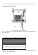

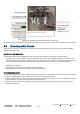


Table Of Contents
- Corning
- Mid-Power Remote Unit (MRU)
- Preface Material
- About This Manual
- Hardware
- Software Warranty
- Returns
- Limitations of Liabilities
- Reporting Defects
- Warnings and Admonishments
- Regulatory Compliance Information
- RF Safety
- Laser Safety
- Care of Fiber Optic Connectors
- Company Certification
- Licensee Contact Information
- Table of Contents
- 1 Introduction
- 2 MRU Interfaces
- 3 Installation Guidelines
- 4 Installation
- 5 Appendix A: Specifications
- Supported Services
- Coupling Specifications
- Physical Specifications
- 6 Appendix B: Ordering Information

Installation CMA-XXX-AEN Page 37
Draft
Connect the open wire dry contact cable (ordered separately) to the MRU ‘External Alarms’ port and to the external input
sources. Refer to Table 4-8 and to Figure 4-18 for pin out information.
Pin Description
1 Common
2 Not connected
3 Not connected
4 Not connected
5 Not connected
6 Door alarm
7 HEX (heat exchange) alarm
8 Future alarm
9
Exist indication (indicates existing
connection of alarm cable)
Table 4-8. MRU External Alarm Connector Pin Out
Description
Figure 4-18. MRU External Alarms Connector Pin Out
Refer to Table 4-9 and Figure 4-19 for dry contact alarms cable wiring description.
Color Description
Red +48 V_COMMON
Green N48 V_EXIST INDICATION
Brown N48 V_DOOR ALARM
Black N48 V_HEX ALARM
White N48 V_FUTURE ALARM
Table 4-9. Dry Contact Alarm Cable Wiring Info
Figure 4-19. Dry Contact Alarm Cable Wiring