
User's Manual

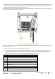

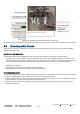
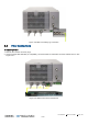


Table Of Contents
- Corning
- Mid-Power Remote Unit (MRU)
- Preface Material
- About This Manual
- Hardware
- Software Warranty
- Returns
- Limitations of Liabilities
- Reporting Defects
- Warnings and Admonishments
- Regulatory Compliance Information
- RF Safety
- Laser Safety
- Care of Fiber Optic Connectors
- Company Certification
- Licensee Contact Information
- Table of Contents
- 1 Introduction
- 2 MRU Interfaces
- 3 Installation Guidelines
- 4 Installation
- 5 Appendix A: Specifications
- Supported Services
- Coupling Specifications
- Physical Specifications
- 6 Appendix B: Ordering Information

Installation CMA-XXX-AEN Page 32
Draft
7. Connect RF antenna coax - (for both 4.3-10 Type “ANTENNA PORT” and “2.5GHz INPUT PORT”) route coax cable with
90
◦
right angle connector through its’ designated knockout (see Figure 4-6) behind and above the MRU chassis and
connect to the corresponding RF port. Refer to Figure 4-11.
8. Route optic fiber from ICU and power cable through designated knockouts (see Figure 4-6) and connect according to
instructions in section 4.4. Refer to Figure 4-11.
Figure 4-11. Example of Routed Connection Cables
Note: For DC power connections – route DC power cable with open wires (without connector) and then wire according to
instructions in section
4.7.2.
9. Perform external alarm connections between MRU and cabinet:
A. Connect the external alarms cable (provided with the MRU) to the chassis’s DB-9 ‘External Alarms’ connector. The
connector provides indications for door opening, heat exchanger (HEX) and one additional input for future use.
Refer to Table 4-5 and to Figure 4-12 for MRU ‘External Alarms’ connector pin out.
Pin Description
1 Common
2 Not connected
3 Not connected
4 Not connected
5 Not connected
6 Door alarm
7 HEX (heat exchange) alarm
8 Future alarm
9 Exist indication (indicates existing connection of alarm cable)
Table 4-5. MRU External Alarm Connector Pin Out Description