
User's Manual


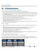

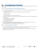
Table Of Contents
- Corning
- Mid-Power Remote Unit (MRU)
- Preface Material
- About This Manual
- Hardware
- Software Warranty
- Returns
- Limitations of Liabilities
- Reporting Defects
- Warnings and Admonishments
- Regulatory Compliance Information
- RF Safety
- Laser Safety
- Care of Fiber Optic Connectors
- Company Certification
- Licensee Contact Information
- Table of Contents
- 1 Introduction
- 2 MRU Interfaces
- 3 Installation Guidelines
- 4 Installation
- 5 Appendix A: Specifications
- Supported Services
- Coupling Specifications
- Physical Specifications
- 6 Appendix B: Ordering Information

Installation Guidelines CMA-XXX-AEN Page 20
Draft
3.6 Antenna Specifications and Guidelines
Determine the antenna installation configuration, according to the transmission and coverage requirements and the installation
site conditions.
3.6.1 Authorized Antennas and Required Specifications
• External antennas - No limitation on any vendor of available external antennas with respect to the following requirements:
• Omni Directional or Directional
• Supported frequency range: wideband antennas supporting a range of 700 MHz to 2600 MHz
• Gain: up to 12.5 dBi
• Impedance: 50 Ohm
• Types of couplers/splitters – depends on number of splits
• Couplers – Use N-Male to N-Female broadband coupler separately ordered from Corning (P/N AK-1COUPLER-NM-NF)
or the equivalent:
• Broadband frequency: 300 – 3000 MHz
• -20 dB coupling (SMA coupling port)
• Max. VSWR/Return Loss:12 dB
• Max. Insertion Loss (dB): 0.2
• Number of antennas that can be connected (with cables/splitters) – it is not recommended to connect more than one
antenna per connector since 1:1 connectivity is reduced with each split.
• Types of couplers/splitters – depends on number of splits (not recommended)
3.6.2 General Installation Guidelines
• The MRU should be installed at a convenient location, free of metallic obstruction (can also be installed in plenum spaces).
• Install the MRU at the designated height and tune it roughly toward the service coverage area.
• Installation of this antenna must provide a minimum separation distance of 100 cm from any personnel within the area.
• Cable and jumper loss is at least 2 dB.