
User's Manual

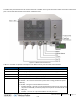
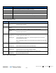

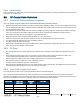

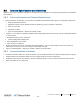
Table Of Contents
- Corning
- Mid-Power Remote Unit (MRU)
- Preface Material
- About This Manual
- Hardware
- Software Warranty
- Returns
- Limitations of Liabilities
- Reporting Defects
- Warnings and Admonishments
- Regulatory Compliance Information
- RF Safety
- Laser Safety
- Care of Fiber Optic Connectors
- Company Certification
- Licensee Contact Information
- Table of Contents
- 1 Introduction
- 2 MRU Interfaces
- 3 Installation Guidelines
- 4 Installation
- 5 Appendix A: Specifications
- Supported Services
- Coupling Specifications
- Physical Specifications
- 6 Appendix B: Ordering Information

MRU Interfaces CMA-XXX-AEN Page 15
Draft
Port Description
Exp. UL/DL
SMA RF ports for UL and DL connections to Add-On unit (supporting any band
across the supported spectrum: 300 MHz to 3 GHz)
List. Mode N/A
OPTIC LC APC port for dual SMF fiber optic connection
MGMT RJ-45 Ethernet connection for MRU local management connection
External Alarms DB-9 female external alarm connector for external dry contact alarm connections
Exp. RJ-45 Ethernet connection for Add-On local craft
Table 2-1. MRU Interface Ports
LED Description
PWR Steady green: Required power is supplied to MRU chassis
Off: No power input detected
RUN Blinking
green:
Unit is running and operational
Rapid blinking
green:
‘Identify’ feature has been enabled via the management GUI
Off: No power inpout detected
STS Steady green: Normal operation; overall status OK
Steady red: Indicates generated alarm in unit
Blinking red: ‘Over temperature’ alarm active.; Indicates temperature has exceeded
threshold (with door open)
Note: Temperature alarm is set as first priority and overrides any other alarm
indicator.
FAM Steady green: All four fans are operating at normal speed (fan alarms clear)
Steady red: Fault detected in at least one fan (fan alarm set)
LINK Steady green: Optical link level from optical module above normal threshold
Steady red: Optical link level is lower than Normal threshold
(PAM)
Steady green:
Power and status of Power Amplifier Module OK. No alarms active.
Steady red: One or more alarms are active.
Table 2-2. MRU LED Descriptions