
User's Manual
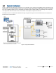

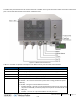
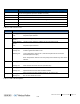

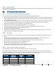

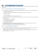
Table Of Contents
- Corning
- Mid-Power Remote Unit (MRU)
- Preface Material
- About This Manual
- Hardware
- Software Warranty
- Returns
- Limitations of Liabilities
- Reporting Defects
- Warnings and Admonishments
- Regulatory Compliance Information
- RF Safety
- Laser Safety
- Care of Fiber Optic Connectors
- Company Certification
- Licensee Contact Information
- Table of Contents
- 1 Introduction
- 2 MRU Interfaces
- 3 Installation Guidelines
- 4 Installation
- 5 Appendix A: Specifications
- Supported Services
- Coupling Specifications
- Physical Specifications
- 6 Appendix B: Ordering Information

MRU Interfaces CMA-XXX-AEN Page 14
Draft
The MRU front panel includes the RF and F/O interfaces in addition to the system level status LEDs and service maintenance
ports. The internal PAM modules each include a PWR/STS LED.
Figure 2-2. MRU External Interfaces
Table 2-1 and Table 2-2 provide a description of the MRU interface ports and LED status indicators.
Port Description
ANTENNA PORT Min DIN 4.3-10 duplexed RF antenna port
TEST PORT QMA coupling test port used for UL and DL measurements during system operation
2.5 GHz INPUT PORT N/A (Future option); Min DIN 4.3-10 RF input port for 2.5 GHz external RF source
GND One two-hole, standard barrel grounding lug
PEM Power Connector Model dependant:
AC models – AC connector connected to power source using provided AC power
cable only
DC models - two types of terminal block connectors:
• CLASS2 (default) – two “DC In” 8-pin terminal block connectors for remote feed:
one pair for each PAM ( total of five pairs) and one pair for the FAM+OPTM; one
RSV pair
• CLASS1 – one “DC-In” 2-pin terminal block for local plant feed