
User's Manual
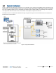


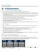

Table Of Contents
- Corning
- Mid-Power Remote Unit (MRU)
- Preface Material
- About This Manual
- Hardware
- Software Warranty
- Returns
- Limitations of Liabilities
- Reporting Defects
- Warnings and Admonishments
- Regulatory Compliance Information
- RF Safety
- Laser Safety
- Care of Fiber Optic Connectors
- Company Certification
- Licensee Contact Information
- Table of Contents
- 1 Introduction
- 2 MRU Interfaces
- 3 Installation Guidelines
- 4 Installation
- 5 Appendix A: Specifications
- Supported Services
- Coupling Specifications
- Physical Specifications
- 6 Appendix B: Ordering Information

Introduction CMA-XXX-AEN Page 11
Draft
1.3 System Architecture
Figure 1-2 illustrates the MRU system architecture. In the downlink, at the headend, the BTS/BDA signal is conditioned at the
headend unit (e.g. integrated headend unit IHU)), by the service specific radio interface modules (RIM), ensuring a constant RF
level. The conditioned signals are then converted by the optical interface modules (OIM) to an optical signal for transporting
over single-mode fiber to the MRU at the remote location. In the uplink, the process is reversed.
All mobile services are combined and distributed through a single antenna port over the broadband antenna infrastructure
installed at the remote locations.
Figure 1-2. System Architecture