® CONTINUOUS FLOW ICEMAKER WCC1401-A/WCF1411-A Series Service Manual Release Date: October 26, 2006 Publication Number: 630460324SER Revision Date: N/A Revision: A Visit the IMI Cornelius web site at www.cornelius.com for all your Literature needs.
CONTINUOUS FLOW ICEMAKER SERVICE MANUAL The products, technical information, and instructions contained in this manual are subject to change without notice. These instructions are not intended to cover all details or variations of the equipment, nor to provide for every possible contingency in the installation, operation or maintenance of this equipment.
TABLE OF CONTENTS Safety . . . . . . . . . . . . . . . . . . . . . . . . . . . . . . . . . . . . . . . . . . . . . . . . . . . . . . . . . . . . . . . Safety Instructions . . . . . . . . . . . . . . . . . . . . . . . . . . . . . . . . . . . . . . . . . . . . . . . . . . . Read and Follow all Safety Instructions . . . . . . . . . . . . . . . . . . . . . . . . . . . . . . . Recognize Safety Alerts . . . . . . . . . . . . . . . . . . . . . . . . . . . . . . . . . . . . . . . . . . . Different Types of Alerts .
Continuous Flow Icemaker Service Manual SAFETY SAFETY INSTRUCTIONS Read and Follow all Safety Instructions Read and follow all safety instructions in this manual and on the machine (decals, labels, and laminated cards). Read and understand all applicable OSHA (Occupation Safety and Health Administration) safety regulations before operating the machine. Recognize Safety Alerts This is the safety alert symbol.
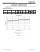
Continuous Flow Icemaker Service Manual GENERAL DESCRIPTION This section gives the Unit description, theory of operation, and design data for continuous flow icemaker series WCC1401-A. SPECIFICATION CHART Models WCC1401-A Description Ice Maker VAC 208/230 HZ 60 PH Wire 1 Refrigerant Comp. RLA Fan Amps GRMTR Amps Oz. Type Circuit Fuse 12.2 1.2 (2) 2.0 (2) 35 404A 20 2 FIGURE 1 Publication Number: 630460324SER -2- © 2006, IMI Cornelius Inc.
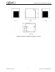
Continuous Flow Icemaker Service Manual FIGURE 2. Series WCC1401-A/WCF1411-A Dimension Drawing © 2006, IMI Cornelius Inc.
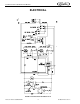
Continuous Flow Icemaker Service Manual ELECTRICAL FIGURE 3. Schematic WCC1401-A/WCF1411-A Publication Number: 630460324SER -4- © 2006, IMI Cornelius Inc.
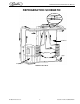
Continuous Flow Icemaker Service Manual REFRIGERATION SCHEMATIC Condenser Evaporator Dryer TXV Compressor FIGURE 4. WCC1401-A © 2006, IMI Cornelius Inc.
Continuous Flow Icemaker Service Manual CLEANING AND SANITIZING ICEMAKER CLEANING AND SANITIZING PROCEDURES Do not use any of the ice made during cleaning operations. Clean and sanitize ice storage area when cleaning icemaker. 1. 2. 3. 4. Turn off machine. Shut off water supply Remove ice from storage bin. Mix approved cleaner (4 gallons as directed). Recommended cleaner: Calgon Nickel-Safe, ice machine cleaner. Mixture: 3 ounces per gallon of water. 5.
Continuous Flow Icemaker Service Manual Semi-Annually Semi-Annually in addition to all previously established service procedures perform the following: 1. 2. 3. 4. 5. 6. 7. Check for water leaks in tube connections, water fittings and lower icemaker water seal. Check drain tubes for clogs and aged tubes. Replace if tubes are stained or brittle. Check for signs of condensation. Clean where necessary and replace insulation properly. Check safety circuits for proper operation. Check refrigeration system.
Continuous Flow Icemaker Service Manual REFRIGERATION SYSTEM 90° 18 20 20 21 23 27 AIR TEMP AIR TEMP. 50° 60° 70° 80° 90° 105° Suction Pressure +- 2 lb. Water Temperature 50° 70° 18 18 20 20 20 20 21 21 23 23 27 27 Discharge Pressure +- 10 lbs.
Continuous Flow Icemaker Service Manual WATER LEVEL CONTROL HOW WATER LEVEL CONTROL WORKS When water is introduced through the inlet fitting the float rises, the float pushes against a lever that in turn, forces the poppet assembly against the inlet fitting valve seat that seals the water off. See Figure 1 (page 7). Before the water inlet is sealed, the safety switch is operated. In the event of a water failure the float would drop down and operate the safety switch to shut off the machine.
Continuous Flow Icemaker Service Manual BIN CONTROL The type of bin control used on all WCC and WCF Models is an electronic control. The control is supplied with power to terminals X1 and X2. Terminals X3 and X4 are a normally closed switch which open when the thermostat sensor bulb senses ice. The WCC1401-A/WCF1401-A uses 2 controls, terminals X1 and X2 are connected in parallel and terminals X3 and X4 are connected in series.
Continuous Flow Icemaker Service Manual GEARMOTOR OVERLOAD TRIPPED Check water level control and evaporator water tube for line build-up restrictions. NO YES CAUTION Clear ice from evaporator and auger before resetting overload. CLEAN See Instructions. Reset overload. IMPORTANT Icemaker runs when reset but problem has not been found. Continue checking for overload as follows to guard against future problems. Icemaker runs. Short run. Trips again in 2 minutes. Check gearmotor circuits.
Continuous Flow Icemaker Service Manual MOTOR CHECK The resistance readings on the winding will be between 5 to 25 ohms. A meter capable of these low readings must be used. The start relay cover must be removed. If no continuity on start or run winding test, replace gearmotor. If continuity on grounded motor test, replace gearmotor. START RELAY 1. 2. Check between “2” and “4” on relay (with relay unplugged). If there is continuity replace the relay, as the relay contacts should be open.
Continuous Flow Icemaker Service Manual AUGER AND EXTRUDING HEAD REMOVAL 1. 2. 3. 4. 5. Disconnect unit from power supply. Remove storage container cover and put aside. Turn off water supply to icemaker. After ice has melted from head take hold of the auger nut and lift straight up to disengage from icemaker. When replacing the auger assembly, make certain that both the auger engages the output shaft drive and the extruding head ribs engage the evaporator tube. INSTALLATION AND SHAFT SEAL REPLACEMENT 1.
Continuous Flow Icemaker Service Manual ELECTRICAL CHECKOUT 1. 2. 3. Be sure the unit is disconnected from the power source. Remove the compressor electrical box cover. Check for obvious damage and loose wires. Disconnect the fan motor leads. Since capacitors store energy, short the capacitor with a screwdriver. This will prevent shocks. Disconnect the compressor terminal wires. OVERLOAD CHECK Using a volt–ohmmeter check the continuity across the overload, contact #1 and #3.
Continuous Flow Icemaker Service Manual GUIDE TO GOOD ICE CUSTOMER COMMENTS CHECK ICEMAKER LOCATION CONDITIONS FIRST “It runs but the ice is too soft.” Proper air flow for condensing system. “The icemaker is not producing enough ice.” Location too close to high units such as coffee urns, deep fryers, grills, etc. “The ice is too wet.” Supply water conditions Water too warm (above 90 o F). Water artificially softened above 262 ppm sodium chloride.
Publication Number: 630460324SER Open valve - 16 - Evacuate and recharge system. Clean condenser. Non-condensible in system. Condenser fan not running. LAC not operating properly (minimum discharge pressure 180 lbs.). Check for leaks. Replace LAC valve, evacuate and recharge system. Remote condenser units only Replace dryer. Evacuate and recharge system. Plugged liquid line dryer. Replace valve. Evacuate and recharge system. Check gears in gearbox. No Check if auger is turning.
Continuous Flow Icemaker Service Manual © 2006, IMI Cornelius Inc.
IMI Cornelius Inc. www.cornelius.