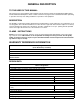
IMI CORNELIUS INC g One Cornelius Place g Anoka, MN 55303-6234 Telephone (800) 238-3600 Facsimile (800) 535-4231 Installation/Service Manual UCR 700 SERIES CONTINUOUS– FLOW ICEMAKER IMPORTANT: TO THE INSTALLER. It is the responsibility of the Installer to ensure that the water supply to the dispensing equipment is provided with protection against backflow by an air gap as defined in ANSI/ASME A112.1.2-1979; or an approved vacuum breaker or other such method as proved effective by test.
TABLE OF CONTENTS Page SAFETY INFORMATION . . . . . . . . . . . . . . . . . . . . . . . . . . . . . . . . . . . . . . . . . . . . . . . . . . . . 1 RECOGNIZE SAFETY INFORMATION . . . . . . . . . . . . . . . . . . . . . . . . . . . . . . . . . . 1 UNDERSTAND SIGNAL WORDS . . . . . . . . . . . . . . . . . . . . . . . . . . . . . . . . . . . . . . . 1 FOLLOW SAFETY INSTRUCTIONS . . . . . . . . . . . . . . . . . . . . . . . . . . . . . . . . . . . . 1 GENERAL DESCRIPTION . . . . . . . . . . . . . . . . . . .
TABLE OF CONTENTS (cont’d) Page UPPER NUT AND BEARING ASSEMBLY . . . . . . . . . . . . . . . . . . . . . . . . . . . . . . . . . 18 TO REPLACE BEARING . . . . . . . . . . . . . . . . . . . . . . . . . . . . . . . . . . . . . . . . . . . . . . 18 ELECTRICAL CHECKOUT . . . . . . . . . . . . . . . . . . . . . . . . . . . . . . . . . . . . . . . . . . . . . . 19 OVERLOAD CHECK . . . . . . . . . . . . . . . . . . . . . . . . . . . . . . . . . . . . . . . . . . . . . . . . . . . 19 COMPRESSOR CHECK . . . .
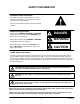
SAFETY INFORMATION Recognize Safety Information This is the safety-alert symbol. When you see this symbol on our machine or in this manual, be alert to the potentially of personal injury. Follow recommended precautions and safe operating practices. Understand Signal Words A signal word - DANGER, WARNING, OR CAUTION is used with the safety-alert symbol. DANGER identifies the most serious hazards. Safety signs with signal word DANGER or WARNING are typically near specific hazards.
THIS PAGE LEFT BLANK INTENTIONALLY 630460154 2
GENERAL DESCRIPTION TO THE USER OF THIS MANUAL This manual covers the installation and assembly of the Air–Cooled or Water–Cooled Model UC700 Icemaker with the Model UC150 Dispenser. Refer to Table of Contents for page location of detailed information pertaining to questions that may arise during installation or operation of this equipment. DESCRIPTION The UC700 is a chuncklet Icemaker designed to be installed under a counter adjacent to an Ice Dispenser or an Ice Storage Bin.
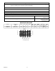
Table 1. Design Data (cont’d) Water Supply–Water inlet fitting is 1/4–inch SAE flare located at the top front of the Unit. The Unit is designed to operate on water pressure between 10 PSI and 90 PSI. Drain Overflow Line (Located at rear of the Unit) 3/8–inch Flexible Tubing Ambient Operating Temperature 40° F to 100° F Electrical: Unit Electrical Rating 115 VAC, 60 Hz, 15.
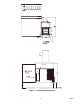
FIGURE 1.
THIS PAGE LEFT BLANK INTENTIONALLY 630460154 6
INSTALLATION PRE–INSTALLATION Freight Damage Claim The delivery of your equipment (Frieght Company, Distributor, or dealer) is responsible for loss or damage of your shipment. All claims must be filed with the deliverer of your equipment. Please follow the steps below to determine if your shipment is satisfactory or if a claim must be filed: 1. Check the number of products delivered against the number of products listed on the delivery receipt.
INSTALLATION 1. Keep unit in the upright position, remove carton and pallet from the Icemaker and inspect for damage. If any damage is found, file a claim with carrier immediately. 2. Locate startup card either on outside of container or on plastic liner. Fill in proper information and send one to factory, and other copy to distributor. Postage is prepaid. 3. Install the Dispenser first, following installation instructions supplied with the Dispenser. 4.
INITIAL START UP, CHECKS AND ADJUSTMENT INSTRUCTIONS NOTE: Do not start Icemaker before completing installation steps on pages 7 and 9. Turn on water supply (if Icemaker is water cooled turn water on to condenser also) turn on main power switch (located on top of electrical box), and make the following system checks: NOTE: If Icemaker will not start be sure water reservoir is full. Low water safety control must be properly adjusted to start and shut down the Icemaker.
THIS PAGE LEFT BLANK INTENTIONALLY 630460154 10
GUIDE TO SERVICE WARNING: Disconnect electrical power to the Icemaker to prevent personal injury before attempting any internal maintenance. Only qualified personnel should service internal components or electrical wiring. ICEMAKER CLEANING AND SANITIZING PROCEDURES Do not use any of the ice made during cleaning operations. Clean and sanitize ice storage area when cleaning icemaker. 1. Turn machine off. 2. Shut off water supply. 3. Remove ice from storage bin. 4.
Semi–Annually Semi-Annually in addition to all previously established service procedures perform the following: 1. Check for water leaks in tube connections, water fittings and lower Icemaker water seal. 2. Check drain tubes for clogs and aged tubes. Replace if tubes are stained or brittle. 3. Check for signs of condensation. Clean where necessary and replace insulation properly. 4. Check safety circuits for proper operation. 5. Check refrigeration system (see page 13). 6. Check unit for abnormal noise.
3. The transparent bowl not only provides a visible check of water level, but also is a good guide to the internal conditions which exist within the icemaker assembly itself. (See Cleaning Procedure.) To Replace Water Level Control 1. Shut off the water supply. Shut off the main power switch or unplug the ice dispenser from electrical outlet. 2. Remove the flexible tubing from bottom of water level control and drain water from water level control and evaporator. 3.
EXPANSION VALVE You will find a thermostatic expansion valve on icemakers, which is used to control the amount of refrigerant flowing through the evaporator. Improperly installed or defective expansion valves may cause low production, soft ice, squeaking from evaporator and excessive load inside evaporator. By using general refrigeration system troubleshooting along with the pressure charts you can easily determine whether or not the expansion valve is working properly.
SIGHT GLASS THERMOSTATIC EXPANSION VALVE FIGURE 5. EXPANSION VALVE FIGURE 6. ADJUSTMENT SCREW CONDENSER MODULATING VALVE REMOVAL 1. Disconnect power to unit, then shut off water supply to condenser and evacuate refrigerant from system. 2. Remove inlet water line from Condenser Modulating Valve. Also remove tube from high side refrigerant line. 3. Remove Condenser Modulating Valve and bracket from unit. 4. Remove valve from bracket. 5. Replace Condenser Modulating Valve by reversing Steps 2 thru 4.
GEARMOTOR The gearmotor is equipped with a start relay and a manual reset overload. When current is applied, the relay energizes and completes the circuit to the start winding. The motor reaches a predetermined speed and the relay drops out, disconnecting the start winding. The run winding remains in the circuit as long as current is applied.
START RELAY 1. Check between “2” and “4” on relay (with relay unplugged). If there is continuity replace the relay, as the relay contacts should be open. 2. Check between “3” and “4” on relay, if no continuity replace the relay. FIGURE 7. GEARMOTOR ASSEMBLY TO REPLACE GEARMOTOR ASSEMBLY 1. Disconnect the icemaker from the electrical power source. 2. Disconnect the transmission cable from the electrical box. 3. Remove the 4 hex head bolts securing the evaporator to the top of the transmission. 4.
AUGER AND EXTRUDING HEAD REMOVAL 1. Disconnect unit from power supply. 2. Remove storage container cover and put aside. 3. Turn off water supply to icemaker. 4. After ice has melted from head take hold of the auger nut and lift straight up to disengage from icemaker. 5. When replacing the auger assembly, make certain that both the auger engages the output shaft drive and the extruding head ribs engage the evaporator tube.
3. Remove Dispense Tray Cover. 4. Use an open end wrench on auger nut connected to bearing and turn counterclockwise to remove assembly. 5. Remove worn bearings. Replace with new bearings and then reinstall assembly. NOTE: If auger turns with nut, remove cover on top of gearmotor stator and hold motor while loosening nut. FIGURE 10. OVERLOAD CHECK FIGURE 11. COMPRESSOR CHECK ELECTRICAL CHECKOUT 1. Be sure the unit is disconnected from the power source. Remove the compressor electrical box cover.
FIGURE 12. GEAR MOTOR OVERLOAD SAFETY CONTROLS Your icemaker unit has several safety and control devices incorporated into its design. WARNING: None of the below described devices should ever be “bypassed” to allow the unit to function. The safety and control system shut-off devices are: 1. Low water shut off reed switch located in icemaker float assembly. (Automatic reset type.) See Figure 3 2. Gearmotor thermal overload, manual reset type (red button on motor). See Wiring Diagram Figure 13. 3.
GUIDE TO GOOD ICE CUSTOMER COMMENTS CHECK ICEMAKER LOCATION CONDITIONS FIRST “It runs but the ice is too soft.” S Proper air flow for condensing system. “The icemaker is not producing enough ice.” S Location too close to high units such as coffee urns, deep fryers, grills, etc. “The ice is too wet.” S Supply water conditions Water too warm (above 90_F). Water artificially softened above 262 ppm sodium chloride. Normal water supply too high in total dissolved solids (above 500 PPM).
630460154 22 FIGURE 13.
TROUBLESHOOTING CHART – ICEMAKER NOT OPERATING NO POWER Check electrical wiring in control box for loose connections. Check for failed service switch or relay. Check power to machine. High pressure switch open or cycling on and off. LOW WATER SAFETY SWITCH OPEN ICEMAKER RUNS BUT DOES NOT MAKE ICE Remote condenser units only Condenser fan running but compressor not running Check electrical wiring in control box for loose connections. Check power to condenser.
TROUBLESHOOTING IMPORTANT: Only qualified personnel should service internal components or electrical wiring. TROUBLESHOOTING COMPRESSORS Trouble Probable Cause Remedy Basically the compressor problems can be narrowed down to three areas of checkout. THE COMPRESSOR WILL NOT RUN THE COMPRESSOR STARTS BUT TRIPS REPEATEDLY ON THE OVERLOAD PROTECTOR THE COMPRESSOR RUNS BUT WILL NOT REFRIGERATE 630460154 A. No voltage to the compressor terminals. A. Check circuit. B. Low voltage. B.
PARTS LIST 25 630460154
2 7 1 1 14 16 6 20 1 17 15 5 1 13 18 11 19 12 10 9 8 FIGURE 14. PANEL COMPONENTS Item No. Part No. Name 1 07578 Thread Cutting Screw, Phil Truss Hd. No. 8–32 X 3/8–in long 2 630000806 Panel Top 3 4 5 630000808 Panel, Left–Hand 6 630000807 Panel, Right–Hand 7 630201094 Panel, Back 8 161176000 Washer, Flat, .250 I.D.
Item No. 4 Part No. Name 2 3 1 Ice Chute Components 9 1 38220 Machine Screw, 1/4-20 8 2 630000741 Elbow, Ice Chute 7 3 630250106 Tube, Ice Transfer 5 4 630900564 O-Ring, 4.234 I.D. 5 630900608 Head, Extruder 6 638090213 Auger 7 638090219 Bearing, Nylon 8 638090220 Bearing, Delrin 9 638090211-002 Auger Nut 6 FIGURE 15. ICE CHUTE COMPONENTS Item No. Part No. Name 2 Water Level Control Components 1 161168017 Machine Screw, Phil Pan Hd, No. 6-32 By 1/4-In.
Item No. 3 Part No. Name Compressor Components 1 1 164154001 Washer, Flat, >375 I.D. 2 165596002 Grommet 2 3 168770002 Machine Screw, Hex Hd, 5/16-18 By 1 1/2-In. Long 4 4 631500018 Compressor Kit 5 638007972-02 Hex Washer Hd, No. 10 By 1/2-In. Long 5 FIGURE 18. COMPRESSOR COMPONENTS Item No. Part No. Name Front End Components 1 161179001 Machine Screw, Hex Hd, 1/2-20 By 5/8-In. Long 2 168833000 Washer, Lock, .255 I.D.
Item No. Part No. 4 5 10 9 Name Evaporator Components 1 630200737 Bracket 2 630900558 Adaptor, Front End Ass’y 3 630900559 Gasket, Front End Ass’y 4 630900572 O-Ring, 4.1 I.D. 5 630900635 Machine Screw, Hex Hd, 1/4-20 By 1 3/4-In. Long 7 6 638001662 Insulator, Switch 7 638003924 Switch 8 638007009-10 Screw, No. 6 By 1 1/4-In. Long 9 638007264-02 Tinnerman Nut 10 638007308-01 Washer 6 2 8 3 1 FIGURE 21. EVAPORATOR COMPONENTS Item No. 2 Part No.
IMI CORNELIUS CERTIFICATE OF WARRANTY TWO YEAR LIMITED ICE EQUIPMENT WARRANTY IMI Cornelius warranty to the original commercial purchaser/user, that any commercial product of its manufacture bearing the name Cornelius will be free from defect in material and/or factory workmanship, and that if properly installed, maintained, and serviced in accordance with the Service Manual furnished with the product, it will perform adequately under normal use.
THIS PAGE LEFT BLANK INTENTIONALLY 31 630460127
IMI CORNELIUS INC.