SPIRAL ICEMAKERâ DISPENSER Operator’s Manual MODELS: SID851A/250S SID851A/250S-B SID851W/250S SID851W/250S-B SID851A/250S-BC SID851W/250S-BC 208--230/115V, 60HZ, 1PH Part No. 90914 August, 1995 Revision D THIS DOCUMENT CONTAINS IMPORTANT INFORMATION This Manual must be read and understood before installing or operating this equipment â REMCOR INC: 1995 PRINTED IN U.S.
TABLE OF CONTENTS Page GENERAL INFORMATION . . . . . . . . . . . . . . . . . . . . . . . . . . . . . . . . . . . . . . . . . . . . . . . . . . 1 DESCRIPTION . . . . . . . . . . . . . . . . . . . . . . . . . . . . . . . . . . . . . . . . . . . . . . . . . . . . . . . . 1 INSTALLATION INSTRUCTIONS . . . . . . . . . . . . . . . . . . . . . . . . . . . . . . . . . . . . . . . . . . . . 2 UNPACKING INSTRUCTIONS . . . . . . . . . . . . . . . . . . . . . . . . . . . . . . . . . . . . . . . . . .
TABLE OF CONTENTS (cont’d) LIST OF TABLES Page TABLE 1. SPECIFICATIONS . . . . . . . . . . . . . . . . . . . . . . . . . . . . . . . . . . . . . . . . . . . . 1 TABLE 2. LBS./24-HOUR ICE PRODUCTION . . . . . . . . . . . . . . . . . . . . . . . . . . . . . TABLE 3. HARVEST CYCLE . . . . . . . . . . . . . . . . . . . . . . . . . . . . . . . . . . . . . . . . . . . .
GENERAL INFORMATION DESCRIPTION The Remcor S.I.D. (Spiral Ice Maker/Dispenser) is a unique, self-contained, counter top style unit that automatically makes hard, clear cube-quality ice and stores it in a sealed hopper for sanitary dispensing. The ice is made by a new, patented process on a spiral-shaped, stainless steel evaporator and produces true cube quality ice on the outside of the tubes.
INSTALLATION INSTRUCTIONS UNPACKING INSTRUCTIONS 1. With the unit upright, carefully remove the shipping crate. Inspect for shipping damage and report any such damage to the shipper immediately. 2. Open the hinged service door and remove shipping tape from the ice drop cover, storage hopper cover and agitator in the storage hopper. 3. Remove shipping tape from air inlet filter and sink grill.
IMPORTANT: To ensure proper ice maker operation and also to reduce the frequency of water-related service problems, a water filter should be installed. Remcor recommends the use of one of the following basic systems: 1. Everpure, Inc. 660 No. Blackhawk Drive Westmont, IL 60559 (708) 654-4000 Insurlce Twin System #9320-42 2.
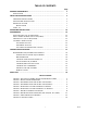
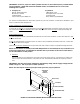
4 90914 60 45 7/8 24 20 1/2 8 15/16 14 *FOR MODELS: SID 851/250 SID 851/250-B 16 1/4 45 1/8 13 1/4 2 1/4 29 1 2 1/2 2 1/2 1 1/2 18 3/4 25 3/8 15 1/8 14 1/2 36 33 1/16 9 3/4 8 1/16 32 1/8 CLEARANCE NECESSARY ONLY IF UNITS ARE INSTALLED IN AN ENCLOSED SPACE. DOOR WITH LOCK FOR ACCESS TO ICE STORAGE AREA. FIGURE 2. INSTALLATION DIMENSIONS 6 12 *ICEMAKER WATER IN 3/8 O.D. TUBE COMP.
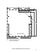
15 7/8-IN. 14-IN. 2 3/4-IN. 3/8 DIA. 10 1/2-IN. 32 1/2-IN. 36-IN. 16-IN. 2 1/8-IN. UNIT OUTLINE FRONT 27 11/16-IN. 32-IN. NOTE: Shaded area indicates opening in bottom for beverage tubing. FIGURE 3.
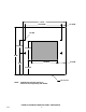
32-IN. 27 11/16-IN. 3 1/16-IN. 1/2 DIA. 10 1/2-IN. 14 1/8-IN. 36-IN. 19 5/8-IN. 16-IN. 5 7/8-IN. 11 1/4-IN. FRONT UNIT OUTLINE NOTE: 90914 Shaded area indicates opening in bottom for beverage tubing and utilities. FIGURE 4.
BEVERAGE SYSTEM “B”models contain beverage faucets only and must be supplied with cold product from any remote cold plate or refrigerated soda factory. “BC”units have a built-in cold plate, in addition to the beverage faucets and are designed to be supplied directly from syrup tanks and carbonator with no additional cooling required. Installation 1. Locate the required openings in the counter top for the beverage lines as shown in Figure 3 (for “B”models) or Figure 4 (for “BC”models). 2.
90914 8 ITEMS OUTSIDE OF BROKEN LINE ARE NOT INCLUDED WITH UNIT 8 7 6 LINE LEGEND CO2 CARB WATER PLAIN WATER SYRUP OPTIONAL 1 2 3 4 4 3 FILTER 2 NON-CARB OR CARB WATER 1 PRIMARY REGULATORS FIGURE 5.
9 90914 LINE LEGEND CO2 CARB WATER PLAIN WATER SYRUP OPTIONAL 8 7 6 5 4 3 2 1 2 3 4 8 1,5,6, 7,8 7 NON-CARB OR CARB WATER 6 5 60-100 PSIG 4 OPTIONAL FOR DIET OR ROOT BEER CARBONATOR FIGURE 6. BEVERAGE SYSTEM SCHEMATIC -BC MODELS ITEMS OUTSIDE OF BROKEN LINE ARE NOT INCLUDED WITH UNIT.
OPERATING INSTRUCTIONS A temperature sensing control bulb located in the storage hopper starts and stops the ice making process in response to ice level in the hopper. With this ice level control “calling”for ice (hopper ice level is low), ice begins to form on the stainless steel tubing coils in the evaporator coils until it contacts the ice thickness probe (low voltage conductivity sensor). At this point, the conductivity probe triggers the harvest timer motor.
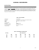
208-230 / 115V, 1PH, (4 WIRE SYSTEM) L1 TP N COMPRESSOR C CC L2 5 R 5 RUN CAP CC 2 START RELAY START CAP STOP / RUN LPS HPS BIN T’STAT 1 CC 2 COMPRESSOR CONTRACTOR HARVEST MOTOR NC RED HT3 C BLUE NO CAP CONDENSER FAN NC HT2 C RUN NO AIR PUMP CLEAN HG SOL VALVE NC HT4 C WATER DUMP VALVE NO FLUSH NO WATER LEVEL PROBE C L N WATER FILL VALVE NC FILL ICE THICKNESS PROBE NO HI C LO COM NC NC HT1 CONDUCTIVITY CONTROL HT C NO NO HT5 VEND SWITCH NC AR C F HA
BLUE WHT HQ SOL VALVE YEL YEL BLUE BRN P I N K BLK PUR NEUTRAL YEL LPS R E D HARVEST TIME O R N FUSE 1-1/4 AMP TIME DELAY BLUE WHT WHT WHT WATER FILL VALVE BLK ORN RED R E D BRN WHT YEL ICE THICKNESS PROBE BLK BLK BLK WHT RED BLUE RED RED AGITATOR MOTOR CAP PINK RED WHT BLUE WATER LEVEL PROBE HARVEST MOTOR CAP.
FIGURE 9.
MAINTENANCE REGULAR BASIS (or as required) Cleaning of the ice maker is recommended on a regular basis not only for sanitary reasons, but also to maintain the performance of the unit. Build-up of lime and scale can hinder ice making production rates and interfere with proper dispensing of the ice. See Cleaning Instructions for the recommended procedure.
6. Push manual water fill switch and fill evaporator with water (approximately 5 seconds). 7. Put the “Clean/Run”switch in the “clean”position. Allow unit to run in the cleaning mode for at least 30 minutes. 8. Put the “Clean/Run”switch in the “run”position. 9. Depress the “Flush”switch push button and drain evaporator for about 1-1/2 minutes. Release push button. Push manual water fill switch and allow evaporator to refill with water.
2. Slide the cold plate cover back. (Remove shipping tape and discard). 3. Remove any debris from the drain trough and spring. Check that drain hole is not clogged. 4. Wash down the inside of the cold plate with a mild detergent solution and rinse. A small, long handled brush will be found helpful in reaching the corners. 5. Slide the cover forward, taking care that it is securely positioned on the cold plate. 6. Replace the lower front panel. Beverage System 1.
TROUBLESHOOTING GUIDE The following pages contain troubleshooting charts designed to aid an experienced service person in diagnosing any operating problem which may be experienced. It is assumed that normal service techniques and skills are familiar to the person doing the troubleshooting. In order to gain maximum benefit from these charts please note: 1. Start at the beginning of the chart and supply the appropriate answer to each question. 2. Do not skip any section, unless instructed to do so.
START DOES UNIT OPERATE? NO OPERATION OF ANY COMPONENT. NO GO TO 1. YES IS ICE MAKER O.K.? ICE MAKER ABNORMAL. DISPENSER AND BEVERAGE WORK NORMALLY. NO GO TO 2. YES IS DISPENSER O.K.? DOES NOT DISPENSE. ICE MAKER WORKS O.K. NO GO TO 3. YES IS BEVERAGE SYSTEM O.K.? PROBLEM WITH BEVERAGE FAUCETS OR DRINK QUALITY. NO GO TO 4.
1. TOTALLY INOPERATIVE YES POWER PRESENT AT REAR JUNCTION BOX? YES CHECK FOR LOOSE CONNECTION OR BROKEN WIRE INSIDE UNIT. NO IS SUPPLY FUSE BLOWN (OR C/B TRIPPED)? NO CHECK FOR LOOSE CONNECTION OR BROKEN WIRE IN SUPPLY WIRING OF UNIT. IS LINE VOLTAGE WITHIN ± 10% OF NAMEPLATE VOLTAGE? NO YES 1. 2. IS FUSE OR C/B SIZE PROPER? YES CHECK FOR SHORT CIRCUIT IN WIRING INSIDE UNIT. CHECK COMPONENTS FOR SHORT CIRCUIT OR GROUNDED WIRING. NO IS LINE VOLTAGE HIGH OR LOW? REPLACE WITH CORRECT SIZE DEVICE.
2. ICE MAKER PROBLEM DOES ICE MAKER OPERATE? NO GO TO 2.A YES YES IS ICE PRODUCED? NO DOES COMPRESSOR RUN? YES IS ICE ON EVAPORATOR? NO NO GO TO 2.B GO TO 2.C IS ICE PRODUCTION NORMAL? YES NO GO TO 2.D GO TO 2.E YES DONE 90914 YES IS ICE QUALITY NORMAL? 20 NO GO TO 2.
2.A ICE MAKER PROBLEM IS HOPPER FULL? YES RUN/STOP SWITCH? RUN STOP PUT SWITCH IN RUN POSITION. NO NORMAL SHUTOFF ON BIN THERMOSTAT. YES 1. 2. IS BIN THERMOSTAT OPEN? NO CHECK THERMOSTAT ADJUSTMENT. REPLACE BIN THERMOSTAT. IS WATER LEVEL NORMAL IN EVAP.? YES IS LOWPRESSURE SWITCH OPEN? YES NO NO NO IS HIGHPRESSURE SWITCH OPEN? YES CHECK FOR LOOSE CONNECTION OR BROKEN WIRE. 1. 2. 3. 4. 5. 6. AIR-COOLED UNITS CHECK THAT WATER SUPPLY IS OPEN. CHECK WATER SUPPLY FILTER.
2.B COMPRESSOR INOPERATIVE IS LINE VOLTAGE WITHIN ± 10% OF NAMEPLATE VOLTAGE? YES IS THERMAL PROTECTOR OPEN? NO IS CONTACTOR PULLED IN? NO YES YES CHECK VOLTAGE PROBLEMS IN 1. YES NO IS COMPRESSOR BODY COLD? 1. NO 2. 3. 4. 5. CHECK FOR LOOSE OR BROKEN WIRING CONNECTION IN COMPRESSOR POWER CIRCUIT. CHECK CONTACTOR. CHECK STARTING RELAY. CHECK CAPACITOR(S). CHECK COMPRESSOR MOTOR. REPLACE THERMAL PROTECTOR. YES IS 120V. PRESENT AT CONTACTOR COIL TERMINAL? REPLACE CONTACTOR. NO 1. 2.
2.C NO ICE ON EVAPORATOR IS HARVEST TIMER RUNNING? NO IS EVAPORATOR COLD? YES NO YES IS HOT GAS SOLENOID ENERGIZED? YES IS WATER LEVEL NORMAL? NO NO YES 1. CHECK WATER PROBLEMS IN 2.A. 2. CHECK REFRIGERATION SYSTEM. YES 3. IS COND. CONTROL ENERGIZED? CHECK FOR REFRIGERANT UNDER-CHARGE. CHECK HOT GAS SOLENOID FOR LEAKING SEAT. GO TO 2.A. NO YES CHECK TIMER SWITCH #1. 1. 2. 1. 2. IS HARVEST TIMER HOME? CHECK FOR OPEN CONDUCT PROBE WIRING. CHECK CONDUCTIVITY CONTROL. 1.
2.D FROZEN EVAPORATOR 1. 2. SHUTOFF ICE MAKER AND THAW EVAPORATOR. START ICE MAKER. IS AMBIENT ABOVE 60°F? 1. NO 2. ARRANGE TO MAINTAIN MINIMUM 60° F AMBIENT. CONDUCT FACTORY REGARDING SPECIAL APPLICATION. YES IS VOLTAGE WITHIN ±10%? NO CHECK VOLTAGE ITEMS IN 1. YES DISCONNECT PROBE WIRE FROM CONDUCTIVITY CONTROL. DOES TIMER START? NO 1. 2. CHECK TIMER MOTOR. CHECK CONDUCTIVITY CONTROL. YES 1. HOT GAS OPERATION O.K.? NO 2. 3. CHECK ADJUSTMENT OF TIMER CAM #2.
2.D (CONT’D) YES NO 1. 2. 3. 4. CHECK ADJUSTMENT OF TIMER CAM #3. (HARVEST MOTOR) CHECK TIMER SWITCH #3. CHECK HARVEST MOTOR CAPACITOR. CHECK HARVEST MOTOR. REPLACE PROBE WIRE ON CONDUCTIVITY CONTROL DURING HARVEST CYCLE. DOES TIMER RETURN HOME? 1. NO 2. CHECK ADJUSTMENT OF TIMER CAM #1. (TIMER HOME) CHECK TIMER SWITCH #1. YES WAIT ONE FULL FREEZING CYCLE (APPROX. 6-10 MIN.) DOES HARVEST INITIATE? 1. NO 2. CHECK PROBE WIRING FOR SHORTED CONNECTION. CHECK CONDUCTIVITY CONTROL.
2.E LOW ICE PRODUCTION IS WATER LEVEL NORMAL? NO CHECK WATER ITEMS IN 2.A. YES IS WATER TEMP. HIGH? YES NORMAL EFFECT. INSTALL REMCOR PRE-COOLER TO INCREASE CAPACITY. YES NORMAL EFFECT. ARRANGE FOR LOWER AMBIENT AIR TEMP. IF POSSIBLE. NO IS AMBIENT TEMP. HIGH? NO IS ICE THIN? YES GO TO 2.C. NO CHECK REFRIGERATION SYSTEM.
2.F POOR ICE QUALITY YES IS ICE CLOUDY? NO NO IS ICE SOFT? DONE YES 1. 2. 3. 4. 5. 6. 7. CHECK AIR PUMP. CHECK ADJUSTMENT OF TIMER CAM #4. (WATER PUMP) CHECK TIMER SWITCH #4. CHECK WATER DUMP VALVE. CHECK WATER FILTER. INCREASE WATER DUMP BY ADJUSTING TIMER CAM #4. INSTALL ADDITIONAL WATER TREATMENT DEVICES FOR SPECIFIC PROBLEM WATER.
3. DISPENSER PROBLEM YES DOES AGITATOR ROTATE? YES NO DOES GATE OPEN? NO 1. 2. 3. NO CHECK MOTOR CAPACITOR. CHECK TIMER SWITCH #5. CHECK AGITATOR MOTOR. 1. 2. 1. IS HOPPER LEVEL TOO HIGH? NO 2. 3. YES 1. 2. 4. CHECK FOR BURNED OUT SOLENOID. CHECK FOR STUCK OR BINDING GATE MECHANISM. CHECK FOR BLOWN SOLENOID FUSE IN ELECTRICAL BOX. IF FUSE IS BLOWN, CHECK FOR STUCK GATE MECHANISM, BURNED OUT SOLENOID, OR LOW VOLTAGE. CHECK VEND SWITCH.
4. BEVERAGE SYSTEM PROBLEM 1. IS ONE OR MORE FAUCETS INOPERATIVE? YES 2. 3. 4. CHECK WIRING CONNECTIONS TO INOPERATIVE FAUCETS. REPLACE INOPERATIVE FAUCETS. CHECK WIRING CONNECTIONS FROM 24V. TRANSFORMER. CHECK 24V. TRANSFORMER. NO IS BEVERAGE COLD? 1. NO 2. CHECK REMOTE COOLING SYSTEM. (-B MODELS) CHECK FOR ICE ON COLD PLATE. (-BC MODELS) YES IS BEVERAGE PROPERLY CARBONATED? NO 3. 4. CHECK CO2 PRESSURE. CHECK CARBONATOR. 1. 2. 3. 4. CHECK WATER SUPPLY PRESSURE. CHECK SUPPLY FILTER.
MAINTENANCE/ADJUSTMENT PROCEDURES THERMOSTAT ALTITUDE ADJUSTMENTS IMPORTANT: Adjust the bin thermostat setting only if storage hopper over fill is a problem. BIN THERMOSTAT 1. Open the hinged service door. 2. The adjustment screw is located below the “Flush”switch on the left side of the electrical box. 3. For altitudes up to 6,000 feet, turn the adjustment screw COUNTERCLOCKWISE as follows: ELEVATION (FEET) 2,000 4,000 6,000 COUNTERCLOCKWISE TURN 1/13 1/6 1/4 4.
ICE THICKNESS ADJUSTMENT WARNING: Do not adjust ice thickness probe unless all other problem causes have been evaluated. 1. Open the hinged service door and remove the ice drop and hopper covers. 2. Collect and weigh the ice produced during the harvest cycle. The amount of ice harvested should weigh approximately five (5) pounds. Use the following procedure to adjust the probe to obtain this weight.
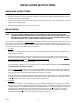
HARVEST TIME ADJUSTMENT WARNING: Disconnect electrical power to the unit before servicing the timer in the electrical box. 1. Disconnect power to ice maker. 2. Open the hinged service door and remove the electrical control box cover. 3. Place the “Stop/Run”switch in the “Stop”position. 4. Using Figure 10 as a guide, set the timer cam tabs as follows, starting with cam wheel No.1 (all cam tab positions are in relation to No.1 left cam tab).
10A FIGURE 10.
PARTS LIST PART NUMBERS DESCRIPTION Dispenser Components Gate Slide Depressor Lever Depressor Retainer Agitator Vend Switch Switch Boot Agitator Motor with Gasket Agitator Motor Shaft Seal Agitator Motor Plate Insulation Sink Sink Grill Ice Chute, Back Section Ice Chute Cover Gate Gasket Gate Solenoid Assembly Gate Rebuilding Kit Agitator Motor Heater Agitator Motor Gasket DESCRIPTION Electrical Controls 250 Air Cooled 250 “BC” 21491 22777 22644 23692 30895 31007 31197-1 50891 50967 51024 70496 53015 5
PARTS LIST (CONT’D) DESCRIPTION Refrigeration Components PART NUMBERS Air Cooled 250 250 “BC” Water Cooled 250 250 “BC” Compressor 60678 60678 60678 60678 Compressor Mounting Kit 31607 31607 31607 31607 Air Pump 31568 31568 31568 31568 Hose Adaptor, 3/8 NPT X 3/8 Barb 51189 51189 51189 51189 Hose Adaptor 90°, 3/8 NPT X 3/8 Barb 51190 51190 51190 51190 Condenser Fan Motor 31738 31738 ---------- ---------- Condenser Fan Blade 31739 31739 ---------- ---------- Water Valve
IMI CORNELIUS INC. ONE CORNELIUS PLACE ANOKA, MN. 55303--6234 TELEPHONE (800) 238--3600 FACSIMILE (612) 422--3232 TECH SVC 1-800-535-4240 WARRANTY IMI Cornelius Inc. and Remcor Products Company warrants that all equipment and parts are free from defects in material and workmanship under normal use and service. For a copy of the warranty applicable to your Cornelius and or Remcor product, in your country, please write, fax or telephone the IMI Cornelius office nearest you.
CORPORATE HEADQUARTERS: Remcor Incorporated 500 Regency Drive Glendale Heights, IL 60139 708. 980.