ICE/BEVERAGE DISPENSERS MODELS: TJ45--A, TJ45--AB TJ90--A, TJ90--AB, TJ90--ABC WITH AUTOMATIC ICE FILLING FROM A REMOTE ICEMAKER SOURCE Operator’s Manual Part No. 90632 Revision H Revised March 21, 1996 THIS DOCUMENT CONTAINS IMPORTANT INFORMATION This Manual must be read and understood before installing or operating this equipment â REMCOR INC: PRINTED IN U.S.
TABLE OF CONTENTS Page SAFETY PRECAUTIONS . . . . . . . . . . . . . . . . . . . . . . . . . . . . . . . . . . . . . . . . . . . . . . . . . . . DESCRIPTION . . . . . . . . . . . . . . . . . . . . . . . . . . . . . . . . . . . . . . . . . . . . . . . . . . . . . . . . . . . . INSTALLATION INSTRUCTIONS . . . . . . . . . . . . . . . . . . . . . . . . . . . . . . . . . . . . . . . . . . . . SINK DRAIN ASSEMBLY . . . . . . . . . . . . . . . . . . . . . . . . . . . . . . . . . . . . . . . . . . . . . . .
SAFETY PRECAUTIONS Always disconnect power to the dispenser before servicing or cleaning. Never place hands inside of hopper or gate area without disconnecting power to the dispenser. Agitator rotation occurs automatically when dispenser is energized. This ice dispenser has been specifically designed to provide protection against personal injury and eliminates contamination of ice. To insure continued protection and sanitation, observe the following: 1.
DESCRIPTION The REMCORâ Ice and Ice/Beverage dispensers with model numbers suffixed with--A, --AB, and --ABC (e.g. model TJ90E--ABC) are designed to be used with one of several remote “piped ice”type machine. This combination automatically provides a continuous supply of sanitary ice at the touch of a lever, In order to complete an automatic filling installation, the following items must be obtained. 1. Icemaker. This must be obtained from the appropriate manufacturer. 2.
INSTALLATION INSTRUCTIONS 1. The ice dispenser must be fastened and sealed to the counter, using the hardware supplied with the unit. The template drawings (Figure NO TAG) indicate openings which must be cut in the counter for the ice feed tube and utilities. Check that the counter mounting surface for the dispenser is level. Apply a continuous bead of NSF approved silastic sealant (Dow 732 or equal) approximately 1/4”inside of the unit outline dimensions, and around all openings.
CLEANING INSTRUCTIONS WARNING: Disconnect power before cleaning. Do not use metal scrapers, sharp objects or abrasives on the surface of the liner, as damage may result. Do not use solvents or other cleaning agents, as they may attack the plastic liner. DISPENSER 1. Clean the ice dispenser interior at least once a month. 2. Lift off agitator assembly and wash and rinse it thoroughly. 3. Carefully remove and disassemble the deflector assembly and wash and rinse all parts. 4.
B. Sanitation Tank -- Fil with a chlorine sanitizing solution in the strength of 1 ounce of household bleach (sodium hypochlorite) to 1 gallon of cold (ambient) potable water (410PPM). 6. Repeat the following procedure on each of the unit’s syrup product lines. A. Connect the cleaning tank to the syrup line to be sanitized and to the CO2 system. B. Energize the beverage faucet until the liquid dispensed is free of any syrup. C.
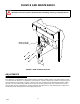
SERVICE AND MAINTENANCE CAUTION: Disconnect power to dispenser before installing, removing or adjusting this kit. INSTALL PLATE ON STUDS AS SHOWN FIGURE 2. GATE RESTRICTOR PLATE ADJUSTMENTS This dispenser is provided with a gate restrictor plate, installed in it highest position. This plate adjusts the rate of ice flow from the dispenser. In applications using buckets, carafes or other large containers, the plate may be removed entirely for maximum ice flow.
TROUBLESHOOTING GUIDE Should your unit fail to operate properly, check that there is power to the unit and that the hopper contains ice. If the unit still does not dispense, check the following chart under the appropriate symptoms to aid in locating the defect. Trouble BLOWN FUSE OR CIRCUIT BREAKER. A. Probable Cause Short circuit in wiring. B. Defective gate solenoid. C. A. Defective agitator motor. No power. B. Bent depressor plate (does not actuate switch). C. A. Defective dispensing switch.
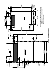
8 90632 1-1/8 IN OUTLINE OF UNIT 1- 1/4 IN 1- 1/8 IN 2 -1/8-DIA. 10- 5/8 IN 6- 17/ 32 IN. 2- 5/16-IN. 5/8 IN. 8* 22-IN. 19-3/4 IN TJ90--AB, ABC 18- 7/8-IN. 2* 4-IN. FIGURE 3. MOUNTING TEMPLATE 15 7/8-IN. 12-5/8 IN TJ45--AB 9-3/4 IN 2* 1-5/8 IN 1-5/8 IN OUTLINE OF UNIT 18-9/16-IN. NOTE: 1)SHADED AREA INDICATE OPENINGS IN CABINET BOTTOM NEEDED FOR UTILITIES AND BEVERAGE TUBING. 2) * INDICATES 1/2” DIA. ACCESS HOLE FOR ICEMAKER CONTROL BULB. 3/8 DIA 3 PLACES 21 -25/32-IN.
9 90632 CW CW 8 7 6 5 4 3 2 1 REMCPR “--B” ICE/BEVERAGE DISPENSER ITEMS OUTSIDE OF BROKEN LINES NOT INCLUDED WITH UNIT. FAUCETS 5--15 PSIG S2 S3 S6 60-100 PSIG S5 CARBONATOR S4 15--50 PSIG SYRUP TANKS S8 REGULATOR NOTE: FOR REFERENCE ONLY -- NOT FOR CONTRUCTION. CO2 TANK WATER SUPPLY OPTIONAL PRESSURE REGULATOR FILTER S7 FIGURE 4.
10 90632 COLD PLATE CW CW 8 7 6 5 4 3 2 1 REMCPR “--B” ICE/BEVERAGE DISPENSER ITEMS OUTSIDE OF BROKEN LINES NOT INCLUDED WITH UNIT. FAUCETS 5--15 PSIG S2 S3 S6 60-100 PSIG S5 CARBONATOR S4 15--50 PSIG SYRUP TANKS S8 REGULATOR NOTE: FOR REFERENCE ONLY -- NOT FOR CONTRUCTION. CO2 TANK WATER SUPPLY OPTIONAL PRESSURE REGULATOR FILTER S7 FIGURE 5.
FIGURE 6. INSTALLATION ROUTE ICEMAKER BULB AS SHOWN FASTEN & SEAL TO COUNTER ELECTRIC CONDUIT DISPENSER DISPENSER DRAIN ICEMAKER ICEMAKER SEE INSTALLATION KIT INSTRUCTION FOR FEED TUBE DETAILS FIGURE 7. FIELD WIRING FIELD WIRING COMPARTMENT LOWER CABINET GRND. BLK. WHT.
STAINLESS DEFLECTOR ICEMAKER BULB -- TOP AGITATION BULB -BOTTOM END OF INSTALLED BULB PROTRUDES APPROX 1/4” TYPICAL ALUMINUM PLATE FIGURE 8. DEFLECTOR ASSEMBLY DEFLECTOR ASSEMBLY INSTALL BARE BULBS AS SHOWN ABOVE AGITATION BULB ICEMAKER BULB WITH INSULATION TUBING UP TO DEFLECTOR INSULATING TUBING UP TO DEFLECTOR FIGURE 9.
DANGER: ELECTRIC SHOCK HAZARD DISCONNECT POWER BEFORE SERVICING UNIT GRN. L N WHT. GRD. * T’STAT IS SHOWN IN WARM POSITION. GATE SOL. “OFF” “ON” MOTOR HEATER 1-1/4 AMP TIME DELAY FUSE. BLK WHT INPUT 3 COLD PLATE MOTOR OPTION 2 WHT C B L U 1 T’STAT* NO NC CAP. R E D BLK AGITATION TIMER R E D WHT LID SWITCH (LID SCREW MUST BE IN PLACE FOR AGITATOR OPERATION) WHT BLK BLK RD RED TERMINAL BOARD TRANS. R E D B AGITATOR L MOTOR U E 24V. KEY SWITCH OPTION CAP.
4 22 24 12 10 11 9 1 18 26 28 2 15 14 23 15 27 FIGURE 11 UPPER SECTION EXPLODED VIEW TJ45 8 16 5 3 20 6 7 13 FIGURE 12 EXPLODED VIEW LOWER SECTION TJ45 90632 14
22 4 12 18 26 14 10 11 21 1 15 28 9 23 15 8 17 2 27 FIGURE 13 EXPLODED VIEW UPPER SECTION TJ90 16 5 3 20 13 6 7 FIGURE 14 EXPLODED VIEW LOWER SECTION TJ90 15 90632
PARTS LIST Item No. Part No. TJ45 -A -AB Part No.
1 2 22 4 3 5 4 22 6 19 18 22 20 21 8 16 15 14 11 10 17 19 13 9 12 7 FIGURE 15. SOLENOID ASSEMBLY Index No. Part No. Qty. Name 1 21493 1 2# 31551 1 Solenoid Mounting Plate Solenoid Service Kit 3 70171 2 8--32 x 3/8 Phil Tr HD Screw 4 70121 2 No.
IMI CORNELIUS INC. ONE CORNELIUS PLACE ANOKA, MN. 55303--6234 TELEPHONE (800) 238--3600 FACSIMILE (612) 422--3232 TECH SVC 1-800-535-4240 WARRANTY IMI Cornelius Inc. and Remcor Products Company warrants that all equipment and parts are free from defects in material and workmanship under normal use and service. For a copy of the warranty applicable to your Cornelius and or Remcor product, in your country, please write, fax or telephone the IMI Cornelius office nearest you.
IMI CORNELIUS INC.