IMI CORNELIUS INC g One Cornelius Place g Anoka, MN 55303-6234 Telephone (800) 238-3600 Facsimile (612) 422-3246 Installation/Service Manual VENTURE POST--MIX DISPENSER W/BUILT--IN COLD CARBONATOR (R--134A REFRIGERANT) IMPORTANT: TO THE INSTALLER. It is the responsibility of the Installer to ensure that the water supply to the dispensing equipment is provided with protection against backflow by an air gap as defined in ANSI/ASME A112. 1.
TABLE OF CONTENTS Page SAFETY INFORMATION . . . . . . . . . . . . . . . . . . . . . . . . . . . . . . . . . . . . . . . . . . . . . . . . . . . . 1 RECOGNIZE SAFETY INFORMATION . . . . . . . . . . . . . . . . . . . . . . . . . . . . . . . UNDERSTAND SIGNAL WORDS . . . . . . . . . . . . . . . . . . . . . . . . . . . . . . . . . . . . 1 1 FOLLOW SAFETY INSTRUCTIONS . . . . . . . . . . . . . . . . . . . . . . . . . . . . . . . . . CO2 (CARBON DIOXIDE) WARNING . . . . . . . . . . . . . . . . . . . . . . . .
TABLE OF CONTENTS (cont’d) Page SANITIZING SYRUP SYSTEMS . . . . . . . . . . . . . . . . . . . . . . . . . . . . . . . . . . . . . CHECKING DROP-IN REFRIGERATION ASSEMBLY CONDENSER COIL FOR RESTRICTIONS . . . . . . . . . . . . . . . . . . . . . . . . . . . . . . . . . . . . . . . . . . . . . . . . . . CHECKING ICE WATER BATH . . . . . . . . . . . . . . . . . . . . . . . . . . . . . . . . . . . . . . . . . . CARBONATOR WATER PUMP YEARLY MAINTENANCE OR AFTER WATER SYSTEM DISRUPTIONS . . . . . . . . . . . . .
TABLE OF CONTENTS (cont’d) Page ONLY SYRUP DISPENSED. . . . . . . . . . . . . . . . . . . . . . . . . . . . . . . . . . . . . . . . . TROUBLESHOOTING REFRIGERATION SYSTEM . . . . . . . . . . . . . . . . . . . . 44 45 COMPRESSOR DOES NOT OPERATE. . . . . . . . . . . . . . . . . . . . . . . . . . . . . . COMPRESSOR WILL NOT STOP AFTER SUFFICIENT ICE BANK IS PRODUCED. (NOTE: ICE BANK SHOULD JUST COVER CONTROL BULB). . . . . . . . . . . . . . . . . . . . . . . . . . . . . . . . . . . . . . . . . . . . . . . .
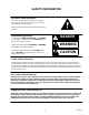
SAFETY INFORMATION Recognize Safety Information This is the safety-alert symbol. When you see this symbol on our machine or in this manual, be alert to the potentially of personal injury. Follow recommended precautions and safe operating practices. Understand Signal Words A signal word - DANGER, WARNING, OR CAUTION is used with the safety-alert symbol. DANGER identifies the most serious hazards. Safety signs with signal word DANGER or WARNING are typically near specific hazards.
THIS PAGE LEFT BLANK INTENTIONALLY 312027000 2
GENERAL INFORMATION IMPORTANT: To the user of this manual - This manual is a guide for installing, operating, and maintaining this equipment. Refer to the Table of Contents for page location for detailed information pertaining to questions that arise during installation, operation, service, or maintenance of this equipment.
WARRANTY REFERENCE INFORMATION Warranty Registration Date (to be filled out by customer) Unit Part Number: Serial Number: Install Date: Local Authorized Service Center: Table 1.
THEORY OF OPERATION (see applicable Figure 2 or 3) WARNING: CO2 displaces oxygen. Strict attention must be observed in the prevention of CO2 (carbon dioxide) gas leaks in the entire CO2 and soft drink system. If a CO2 gas leak is suspected, particularly in a small area, immediately ventilate the contaminated area before attempting to repair the leak. Personnel exposed to high concentration of CO2 gas will experience tremors which are followed rapidly by loss of consciousness and suffocation.
312027000 6 WATER PUMP DOUBLE LIQUID CHECK VALVE CO2 CHECK VALVE LINE LEGEND CO2 PLAIN WATER CARB WATER SYRUP CARBONATOR WATER TANK DISPENSER CAP NUT FIGURE 2.
7 312027000 LINE LEGEND CO2 PLAIN WATER CARB WATER SYRUP CARBONATOR PLAIN WATER INLET CARBONATED WATER TANK CO2 INLET PLAIN WATER NO. 3 VALVE SYRUP 6 SYRUP 5 SYRUP 4 SYRUP 3 SYRUP 2 SYRUP 1 TANKS OR BAG-IN-BOX SYSTEM NOTE: SYRUP SOURCE MAY BE SYRUP CARBONATOR WATER TANK CARB WATER MANIFOLD DISPENSER 6 5 4 3 FIGURE 3.
THIS PAGE LEFT BLANK INTENTIONALLY 312027000 8
INSTALLATION This section covers unpacking and inspection, selecting location, installing the Unit, preparing the Unit for operation, and Unit operation. UNPACKING AND INSPECTION NOTE: The Unit was thoroughly inspected before leaving the factory and the carrier has accepted and signed for it. Any damage or irregularities should be noted at the time of delivery (or not later than 15 days from date of delivery) and immediately reported to the delivering carrier.
SELECTING LOCATION CAUTION: This Unit is intended for indoor installation only. Do not install this Unit in an outdoor environment which would expose it to the outside elements. This Unit may be island-mounted or installed on a front or rear counter.
DISPENSING VALVE RELEASE LATCH DISPENSING VALVE BLOCK SYRUP INLET TUBES (6) FIGURE 4.
IMPORTANT: TO THE INSTALLER. It is the responsibility of the Installer to ensure that the water supply to the dispensing equipment is provided with protection against backflow by an air gap as defined in ANSI/ASME A112. 1.2-1979; or an approved vacuum breaker or other such method as proved effective by test. Water pipe connections and fixtures directly connected to a potable water supply shall be sized, installed, and maintained according to Federal, State, and Local laws.
1. Route syrup source lines from the syrup tanks location up to location under the countertop. 2. Route syrup source lines up through hole cut in the countertop to the barbed and labeled syrup inlet lines on front of the Unit. 3. Connect the syrup source lines to the Unit barbed and labeled syrup inlet lines. Secure connections with tubing clamps. CONNECTING CO2 SOURCE LINE TO UNIT (see applicable Figure 2 or 3 and Figure 4) 1. Route CO2 source line up to back side of the Unit. 2.
3. Install plug in water fill hole. 4. 115 VAC, 60 HZ Units. Make sure the main power switch on right side of the Unit (see Figure 5) is in the “OFF”position. 115 VAC, 60 HZ Units and 230 VAC, 50 HZ Units. Make sure the carbonator water pump motor power switch located on the drop-in refrigeration assembly electrical control box (see Figure 5) is in the “OFF”position. WARNING: Unit must be electrically grounded to avoid possible fatal electrical shock or serious injury to the operator.
3. Open the plain water inlet supply line shutoff valve. Check for water leaks and tighten any loose connections. 4. Place the carbonator water pump motor power switch (located on the refrigeration assembly control box) in the “ON”position. The carbonator water pump will start and continue to operate until the carbonated water tank has been filled, then the water pump motor will stop. Check for CO2, plain water, and carbonated water leaks and tighten any loose connections. 5.
THIS PAGE LEFT BLANK INTENTIONALLY 312027000 16
OPERATOR’S INSTRUCTIONS This section covers operating controls, daily pre-operation check, Unit operation, adjustments, replenishing CO2 and syrup supplies, cleaning and sanitizing, checking the drop-in refrigeration assembly condenser coil for restrictions, checking the ice water bath, water pump yearly maintenance, and periodic cleaning of the CO2 gas check valves. WARNING: Disconnect electrical power to the Unit to prevent personal injury before attempting any internal maintenance.
2. Make sure there is a sufficient syrup supply. If not, replenish the syrup supply as instructed in SERVICE AND MAINTENANCE section in this manual. 3. Make sure drip tray and cup rest are clean and are properly installed on the Unit. UNIT OPERATION 1. Make sure dispensing valves keyed lock-out switch on left side of the Unit is in the “ON”(vertical) position. 2. Press cup or glass against the dispensing valve lever and dispense until the cup or glass is full of product, then release the lever. 3.
SANITIZING SYRUP SYSTEMS The syrup systems should be sanitized as instructed every 90-days. Refer to SERVICE AND MAINTENANCE section in this manual for sanitizing instructions. CHECKING DROP-IN REFRIGERATION ASSEMBLY CONDENSER COIL FOR RESTRICTIONS NOTE: Circulating air required to cool the refrigeration assembly condenser coil is drawn in through the grille on front and is exhausted through grille on top of the hood. Restricting air in or out of the Unit will decrease its cooling efficiency.
THIS PAGE LEFT BLANK INTENTIONALLY 312027000 20
SERVICE AND MAINTENANCE This section describes service and maintenance procedures to be performed on the Unit. IMPORTANT: Only qualified personnel should service internal components or electrical wiring. WARNING: Disconnect electrical power to the Unit to prevent personal injury before attempting any internal maintenance. Only qualified personnel should service the internal components or electrical wiring.
AGITATOR MOTOR HOOD RETAINING SCREW (1) COMPRESSOR CONDENSER FAN MOTOR BUILT-IN COLD CARBONATOR POWER CORD CONDENSER COIL CONTROL BOX WATER FILL HOLE PLUG DISPENSING VALVES KEYED-LOCK SWITCH DISPENSING VALVE SYRUP FLOW REGULATOR DISPENSING VALVE LEVER DISPENSING VALVE COVER WITH WATER LEVER CUP REST FRONT PANEL WATER PUMP MOTOR WATER PUMP SHIPPING NUT (4) MAIN POWER SWITCH (115VAC UNIT ONLY) DRIP TRAY DISPENSING VALVE RELEASE LATCH MOUNTING BLOCK FIGURE 5.
NOTE: To readjust CO2 regulator to a lower setting, loosen adjusting screw lock nut, then turn screw to the left (counterclockwise) until pressure gage reads 5 psi lower than new setting will be. Turn the adjusting screw to the right (clockwise) until the gage registers new setting, then tighten the lock nut. Adjusting Carbonator CO2 Regulator. Adjust primary CO2 regulator (regulator controls Unit built-in cold carbonator CO2 pressure) to a nominal 80 psig. Check for CO2 leaks and repair if evident.
4. Install syrup separator on dispensing valve in place of the nozzle. 5. Measure the water flow rate by dispensing water into a graduated cup for a set period of time. Factory-set flow rate is approximately 1.25 ounces per second. 6. Adjust the water flow control adjusting screw clockwise for a greater flow or counterclockwise for lesser flow. Limit your adjustment to 1/4 turn at a time, then recheck the flow rate. Only the water flow rate is to be adjusted now.
ADJUSTING WATER-TO-SYRUP “RATIO” (BRIX) OF DISPENSED PRODUCT SF-1 Dispensing Valve. (see Figure 6) NOTE: Make sure the dispensing valve water flow rate is as desired before adjusting the valve for Water-to-Syrup ‘‘Ratio’’(Brix) of the dispensed product. Adjust Water-to-Syrup ‘‘Ratio’’of dispensed product by using Ratio Cup (P/N 311100000) and Syrup Diversion Tube Assembly (P/N 319540000) as follows. 1. Remove acorn nut securing the dispensing valve cover, then remove cover from the valve. 2.
5. Adjusting Syrup Flow Regulator -- If water and syrup levels are uneven in the ratio cup, adjust by turning the dispensing valve syrup flow regulator adjusting screw labeled SYRUP as follows. A. For less syrup, turn the adjusting screw counterclockwise no more than 1/4 turn at a time. B. For more syrup, turn the adjusting screw clockwise no more than 1/4 turn at a time. 6.
CLEANING WATER TANK (see Figure 5 and 8) 1. Unplug Unit power cord from electrical outlet. 2. Shut off plain water supply to the Unit. 3. Note pressure setting on the primary CO2 regulator for the carbonator, then turn the regulator adjusting screw to the left (counterclockwise) until gage reads 0-psig. 4. Remove the Unit hood by loosening screw on top of the hood, then lift the hood straight up off the Unit. 5. Disconnect the drop-in refrigeration assembly power cord from the Unit power cord. 6.
24. Plug Unit power cord into electrical outlet. 25. Dispense from one of the carbonated drink dispensing valves to bleed all air from the Unit carbonated water tank and the carbonated water system. 26. Check for leaks and repair if evident. 27. Install hood and secure with screw. CARBONATOR SENSOR LEADS CARBONATOR TANK RELIEF VALVE FIGURE 8. WATER TANK CLEANING AND SANITIZING DAILY CLEANING OF UNIT 1. Remove cup rest from the drip tray. 2.
5. Remove nozzle and syrup diffusers from the dispensing valves. Place nozzles and syrup diffusers in sanitizing solution. 6. Wash the nozzles and syrup diffusers in sanitizing solution, then rinse them with potable water. 7. Re-install nozzles and syrup diffusers back on the dispensing valves. SANITIZING POST-MIX SYRUP SYSTEMS IMPORTANT: Only qualified Service Personnel should perform sanitizing procedure on the post-mix syrup systems.
Fill five-gallon container with potable water, then place all bag-in-box syrup containers syrup outlet tubes in container containing potable water. 9. Flush detergent solution out of the syrup system and dispensing valve as follows: A. Place waste container under applicable dispensing valve. B. Activate the dispensing valve for one minute to purge all detergent solution and flush out the syrup system. C.
Place all bag-in-box syrup containers syrup outlet tubes in container containing potable water. 20. Flush sanitizing solution from the syrup system and the dispensing valve as follows: A. Place waste container under applicable dispensing valve. B. Activate the dispensing valve for one minute to purge all sanitizing solution out of the syrup system and the dispensing valve. C. Continue to activate the dispensing valve in cycles (“ON”for 15-seconds, “OFF”, then “ON”for 15-seconds).
Servicing Water Pump Water Inlet Strainer Screen (see Figures 5 and 9) 1. Unplug Unit power cord from electrical outlet. 2. Remove the Unit hood by loosening one screw on top of the hood, then lift the hood up and off the Unit. 3. Close the water inlet supply line shutoff valve. 4. Note pressure setting on the carbonator primary CO2 regulator, then turn the regulator adjusting screw to the left (counterclockwise) until the gage reads 0-psig. 5.
WATER LINE TO TANK WHITE TAPERED GASKET DOUBLE-LIQUID CHECK VALVE ELBOW PUMP TO MOTOR COUPLING WATER PUMP WATER STRAINER SCREEN (P/N 315348000) O-RING (P/N 315349000) SCREEN RETAINER FIGURE 9. WATER STRAINER SCREEN AND DOUBLE-LIQUID CHECK VALVE 8. Connect the carbonated water line to the double-liquid check valve. 9.
4 3 1 4 2 3 1 2 Item No. Part No. Name 1 5470E Flat Washer 2 312418000 Ball Seat (Quad Ring) 3 312419000 Ball 4 5470D Spring FIGURE 10. LIQUID CHECK VALVE ASSEMBLY NOTE: When indicator on the CO2 cylinder primary CO2 regulator assembly 1800-psi gage is in the shaded (‘‘change CO2 cylinder’’) portion of the dial, the CO2 cylinder is almost empty and should be changed. 1. Fully close (clockwise) the CO2 cylinder main shutoff valve. 2.
SYRUP TANK SYSTEM 1. Disconnect empty syrup tank from syrup system. 2. Check syrup drink quick disconnects for sticky or restricted operation. Wash disconnects in warm water. 3. Connect full tank of syrup into syrup system. BAG-IN-BOX SYRUP SYSTEM 1. Disconnect empty bag-in-box container from syrup system. 2. Check bag-in-box connecter for sticky or restricted operation. Wash bag-in-box connecter in warm water. 3. Connect full bag-in-box container into syrup system. SYRUP FLAVOR CHANGE 1.
THE GERMAN ICE BANK CONTROL IS FOR INTERNATIONAL USE ONLY. FIGURE 12.
37 312027000 FIGURE 13. WIRING DIAGRAM (50 AND 60 HZ UNIT WITH 1/3 H.P.
312027000 38 FIGURE 14. WIRING DIAGRAM (60 HZ UNIT WITH 1/4 H.P.
39 312027000 FIGURE 15. WIRING DIAGRAM (50 HZ UNIT WITH 1/4 H.P.
SOLENOID WHITE FRONT TOP VIEW BLACK 1 BLACK 2 SWITCH C N.O. N.C. RIGHT SIDE VIEW FIGURE 16. WIRING DIAGRAM (SF-1 DISPENSING VALVE) SOLENOID WHITE TWO - PIN CONNECTOR 2 1 BLACK RED P/N 1933 C NO SWITCH ASS’Y P/N 1932 LEVER P/N 1925 FIGURE 17.
THIS PAGE LEFT BLANK INTENTIONALLY 41 312027000
TROUBLESHOOTING IMPORTANT: Only qualified personnel should service internal components or electrical wiring. WARNING: If repairs are to be made to a product system, remove quick disconnects from the applicable product tank, then relieve the system pressure before proceeding. If repairs are to be made to the CO2 system, stop dispensing, shut off the CO2 supply, then relieve the system pressure before proceeding.
Trouble Probable Cause Remedy ADJUSTMENT OF DISPENSING VALVE SYRUP FLOW CONTROL DOES NOT DECREASE TO DESIRED WATER-TO-SYRUP “RATIO”. A. Dirty or inoperative dispensing valve syrup flow control. A. Disassemble and clean dispensing valve syrup flow control. DISPENSED PRODUCT CARBONATION TOO LOW. A. Carbonator CO2 regulator out of adjustment for existing water conditions or temperature. A. Adjust carbonator CO2 regulator as instructed. B. Air in carbonated water tank. B.
Trouble DISPENSED PRODUCT PRODUCES FOAM AS IT LEAVES DISPENSING VALVE.(CONT’D) Probable Cause F. Dirty water supply. Remedy F. Check water filter. Replace cartridge (see NOTE). NOTE: If water supply is dirty, be sure to flush lines and carbonator completely. It may be necessary to remove lines to carbonator tank, invert tank, and flush the tank and all inlet lines to remove any foreign particles or dirt. NO PRODUCT DISPENSED FROM ALL DISPENSING VALVES. ONLY CARBONATED WATER DISPENSED.
TROUBLESHOOTING REFRIGERATION SYSTEM Trouble COMPRESSOR DOES NOT OPERATE. COMPRESSOR WILL NOT STOP AFTER SUFFICIENT ICE BANK IS PRODUCED. (NOTE: ICE BANK SHOULD JUST COVER CONTROL BULB). Probable Cause Remedy A. Ice bank sufficient. A. Refrigeration not called for. B. Unit power cord unplugged, power switch (if applicable) in “OFF”position, or drop-in refrigeration assembly power cord unplugged. B. Plug in power cord(s) or place Unit power switch in “ON” position. C.
Trouble COMPRESSOR OPERATES CONTINUOUSLY BUT DOES NOT FORM SUFFICIENT ICE BANK. Probable Cause Remedy A. Cooling capacity is exceeded by over-drawing. A. Reduce amount of drinks drawn per given time. B. Unit located in excessively hot area or air circulation through condenser coil is restricted. B. Relocate unit or check and if necessary, clean condenser coil as instructed. NOTE: Ice bank freezes from bottom of evaporator upward.
WARRANTY IMI Cornelius Inc. warrants that all equipment and parts are free from defects in material and workmanship under normal use and service. For a copy of the warranty applicable to your Cornelius, Remcor or Wilshire product, in your country, please write, fax or telephone the IMI Cornelius office nearest you. Please provide the equipment model number, serial number and the date of purchase. IMI Cornelius Offices AUSTRALIA D P.O.
IMI CORNELIUS INC.