
Installation manual


Refrigeration Compressor Kit Installation Manual
Publication Number: 3724INS - 5 - © 1994-2012, IMI Cornelius Inc.
COMPRESSOR KIT INSTALLATION
REMOVING OLD COMPRESSOR AND DUAL INLET STRAINER/DRIER
Removal of Refrigerant- In starting work, be advised that the following notes are directly applicable:
NOTE: Do not change compressor until it is proven inoperative.
!
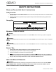
WARNING:
Only trained and certified electrical, plumbing and refrigeration technicians should service this unit.
All wiring and plumbing must conform to national and local codes. Failure to comply could
result in serious injury, death or equipment damage.
!
WARNING:
Disconnect power to the unit before servicing. Follow all lock out/tag out procedures established by the user. Verify all
power is off to the unit before performing any work.
Failure to comply could result in serious injury, death or damage to the equipment.
NOTE: Environmental Protection Agency (EPA) Federal Government rules for refrigerant recovery
must be followed and carried out by certified Personnel. If you have any questions, contact your
employer or the EPA.
!
WARNING:
To avoid possible fatal electric shock or serious injury, disconnect electrical power from the unit before starting kit
installation.
!
WARNING:
To avoid electrical shock even after electrical power has been disconnected from the Unit, discharge the start
capacitor by momentarily touching both terminals at the same time using an insulated screwdriver.
1. Tag electrical wires connected to the compressor for identification.
Remove refrigerant gas from refrigeration system as follows:
IMPORTANT: Do not vent refrigerant gas to the atmosphere. A Refrigerant Recovery System must be
used to reclaim refrigerant from the refrigeration system.
NOTE: Work in a well-ventilated area. Fumes from brazing may contain toxic gases.
NOTE: The line-tapping valves are to be temporarily installed in the refrigeration system to con-
nect the Refrigerant Recovery System to the refrigeration system. After refrigerant recovery has
been completed, remove the line-tapping valves.
NOTE: To maintain factory warranty, do not permanently install line-tapping valves or poppet-type
valves in the refrigeration system. These valves have a potential for leaks.
2. At the compressor, install a line-tapping valve in the suction process line as shown in Figure 1.
3. At the dual inlet drier, install a second line-tapping valve on the discharge process line as shown in Figure 1.
!
WARNING:
To avoid eye injury, wear protective glasses or goggles while working with refrigerant or brazing.
4. Connect Refrigeration gauges and Manifold Set to both of the line tapping valves installed in the process lines.
5. Connect Refrigerant Recovery System to the Refrigeration Gauges and Manifold Set, then reclaim refrigerant
from the refrigeration system.
6. Disconnect Refrigerant Recovery System, then connect dry nitrogen source to the Refrigeration Gauges and
Manifold Set. Break refrigeration system vacuum with dry nitrogen to “0” PSIG.
7. Disconnect Refrigeration Gauges and Manifold Set from both of the line tapping valves installed in the process
lines.