IMI CORNELIUS INC. One Cornelius Place Anoka, MN 55303–6234 Telephone (800) 238–3600 Facsimile (612) 422–3232 Service Manual FCB OVERCOUNTER POST-MIX DISPENSER WITH V3+FEATURES (R-404A REFRIGERANT) IMPORTANT: TO THE INSTALLER. It is the responsibility of the Installer to ensure that the water supply to the dispensing equipment is provided with protection against backflow by an air gap as defined in ANSI/ASME A112. 1.2-1979; or an approved vacuum breaker or other such method as proved effective by test.
TABLE OF CONTENTS Page GENERAL DESCRIPTION . . . . . . . . . . . . . . . . . . . . . . . . . . . . . . . . . . . . . . . . . . . . . . . . . . 1 GENERAL DESCRIPTION . . . . . . . . . . . . . . . . . . . . . . . . . . . . . . . . . . . . . . . . . . . . . . 1 UNIT DESCRIPTION . . . . . . . . . . . . . . . . . . . . . . . . . . . . . . . . . . . . . . . . . . . . . . . . . . . 1 THEORY OF OPERATION . . . . . . . . . . . . . . . . . . . . . . . . . . . . . . . . . . . . . . . . . . . . . .
TABLE OF CONTENTS (cont’d) Page ADJUSTMENT AND PROGRAMMING MAIN MENU SELECTIONS, COMPONENTS “DIAGNOSE’’ (DIAGNOSTIC MODE), AND ‘‘TOTALS”(DISPLAYED CYCLES AND HOURS TOTALS) INTO UNIT . . . . . . . . . . . . . . . . . . . . . . . . . . . . . . . . . . . . . . . . . . . 16 PROGRAMMING MAIN MENU SELECTION ONTO MESSAGE DISPLAY 16 SETTING CLOCK (TIME OF DAY) . . . . . . . . . . . . . . . . . . . . . . . . . . . . . . . . . . . 16 PROGRAMMING ‘‘DEFROST’’ (AUTOMATIC) SETTINGS INTO UNIT . . .
TABLE OF CONTENTS (cont’d) Page REPLENISHING SYRUP SUPPLY . . . . . . . . . . . . . . . . . . . . . . . . . . . . . . . . . . . . . . . 32 PRODUCT FLAVOR CHANGE . . . . . . . . . . . . . . . . . . . . . . . . . . . . . . . . . . . . . . . . . . 33 CHECKING CO2 SUPPLY . . . . . . . . . . . . . . . . . . . . . . . . . . . . . . . . . . . . . . . . . . . . . . 33 CLEANING AND SANITIZING . . . . . . . . . . . . . . . . . . . . . . . . . . . . . . . . . . . . . . . . . . . 33 DAILY CLEANING . . . . . . .
TABLE OF CONTENTS (cont’d) Page SIDE PANELS . . . . . . . . . . . . . . . . . . . . . . . . . . . . . . . . . . . . . . . . . . . . . . . . . . . . 37 FRONT ACCESS PANEL . . . . . . . . . . . . . . . . . . . . . . . . . . . . . . . . . . . . . . . . . . 38 OPENING AND CLOSING FRONT ACCESS DOOR . . . . . . . . . . . . . . . . . . . . . . . 38 OPENING FRONT ACCESS DOOR . . . . . . . . . . . . . . . . . . . . . . . . . . . . . . . . . 38 CLOSING FRONT ACCESS DOOR . . . . . . . . . . . . . . . . . . . .
TABLE OF CONTENTS (cont’d) Page FREEZE CYLINDER AUTOMATIC DEFROST CYCLE DOES NOT OPERATE. . . . . . . . . . . . . . . . . . . . . . . . . . . . . . . . . . . . . . . . . . . . . . . . . . . . . . . . 65 UNIT DOES NOT GO OFF AUTOMATIC DEFROST CYCLE. . . . . . . . . . . . 65 MANUAL DEFROST CYCLE DOES NOT OPERATE WHEN ‘‘DEFROST’’ SWITCH IS PRESSED. . . . . . . . . . . . . . . . . . . . . . . . . . . . . . . . . . . . . . . . . . . . .
TABLE OF CONTENTS (cont’d) Page LIST OF FIGURES (CONT’D) FIGURE 19. CONTROL BOX COMPONENTS . . . . . . . . . . . . . . . . . . . . . . . . . . . . . 73 FIGURE 20. SECONDARY CO2 REGULATOR ASS’Y . . . . . . . . . . . . . . . . . . . . . . 74 FIGURE 21. TUBE ASSEMBLY . . . . . . . . . . . . . . . . . . . . . . . . . . . . . . . . . . . . . . . . . . 74 FIGURE 22. TUBE ASSEMBLY . . . . . . . . . . . . . . . . . . . . . . . . . . . . . . . . . . . . . . . . . . 74 FIGURE 23. CO2 REGULATOR ASSEMBLY . . .
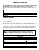
GENERAL DESCRIPTION IMPORTANT: To the user of this manual – This manual is a guide for installing, operating, and maintaining this equipment. Refer to Table of Contents for page location of information pertaining to questions that arise during installation, operation, service and maintenance, or troubleshoo musting this equipment. These Units must be installed and serviced by a qualified Service Person. These Units contain no User serviceable parts.
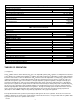
Table 1. Design Data (cont’d) Refrigeration System: Compressor Horsepower Refrigerant Type And Charge 2 H.P. See Unit Nameplate Ambient Operating Temperature 40° F to 100° F Electrical Requirements: Operating Voltage See Unit Nameplate See Unit Nameplate Operating Current Table 2.
Transparent faceplate, attached to the front of each freeze cylinder, includes a self-closing dispensing valve and a spring-loaded relief valve that protects freeze cylinder from accidental over pressure. The relief valve is also used to bleed CO2 gas pressure from the freeze cylinder to atmosphere when filling the cylinder with product. Electronic sensing on each freeze cylinder motor provides a means of adjusting viscosity (consistency) of the dispensed product to suit customer preference. FIGURE 1.
‘‘SLEEP’’ (SLEEP TIME) ‘‘SLEEP’’ (SLEEP TIME) may be programmed into Unit to allow Unit to go into sleep time (Unit shut down, freeze cylinders beaters and refrigeration systems not operating). At start of sleep time, refrigeration compressor will operate for 30 seconds to pump freon out of freeze cylinders evaporator coils, then No. 1 freeze cylinder will go into defrost for 60 seconds. After No. 1 freeze cylinder has defrosted, No. 2 freeze cylinder will go into defrost for 60 seconds. At the end of No.
*WATER PRESSURE REGULATOR IS FACTORY ADJUSTED TO 45-PSI AND SHOULD NOT BE READJUSTED. PRODUCT SAMPLE VALVE(2) **SYRUP SOLD-OUT SWITCHES ARE FACTORY ADJUSTED AND SHOULD NOT BE READJUSTED.
THIS PAGE LEFT BLANK INTENTIONALLY 312028000 6
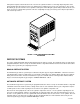
INSTALLATION This section covers unpacking and inspection, installing Loose-Shipped Parts, selecting location, installing Unit, preparing for operation, and operation. UNPACKING AND INSPECTION (see Figure 5) NOTE: The Unit was thoroughly inspected before leaving the factory and the carrier has accepted and signed for it. Any damage or irregularities should be noted at time of delivery (or not later than 15 days from date of delivery) and immediately reported to the delivering carrier.
3. Cleaning brush (item 3) is used to clean faceplate relief valves passages. 4. Tapered gasket, black (item 4) is used to seal connection when connecting plain water source line to Unit water inlet line. 5. Drip tray supports (item 7 and item 8) are to be installed on front of Unit (See Figure 5) and secured with thread cutting screws (item 6) and thread cutting screw (item 16). 6. Cup rest (item 5) is to be installed in drip tray (item 9), then drip tray is to be installed on drip tray supports. 7.
Locate the Unit so the following requirements are satisfied. 1. Close to a filtered plain water inlet supply line with a minimum water pressure of 12-psig. NOTE: The FCB Dispenser refrigeration system is equipped with a condenser coil that is cooled by two condenser coil fans. Circulating air, required to cool the refrigeration system’s condenser coil, is drawn in through the grilled panel on the right-hand side and is exhausted out through the opposite side grilled panel.
INSTALLING PRIMARY CO2 REGULATOR ASSEMBLY ON CO2 CYLINDER (see Figure 2) WARNING: To avoid personal injury and/or property damage, always secure CO2 cylinder in upright position with a safety chain to prevent it from falling over. Should the valve become accidentally damaged or broken off, CO2 cylinder can cause serious personal injury. WARNING: CO2 displaces oxygen. Strict attention must be observed in the prevention of CO2 (carbon dioxide) gas leaks in the entire CO2 and soft drink system.
2. Connect the CO2 source line to the Unit CO2 inlet line. DO NOT TURN ON THE CO2 SOURCE AT THIS TIME. CONNECTING CITY PLAIN WATER SOURCE LINE TO UNIT NOTE: The Units require connection to a city plain water source line with a minimum water pressure of 12-psig. IMI Cornelius Inc. recommends that a water shutoff valve and water filter be installed in the City plain water source line (see Figure 2). A Cornelius Water Filter (P/N 313860000) and Quick Disconnect Set (P/N 313867000) are recommended. 1.
PREPARATION FOR OPERATION TURNING ON ELECTRICAL POWER TO UNIT Turn on electrical power to the Unit. Operational status of the Unit is now being displayed as fault messages on the control panel message display. The following fault messages will be continuously displayed at 2-second intervals until necessary operation requirements are satisfied. ‘‘OFF 1’’ (Beater Motor No. 1 not operating) ‘‘OFF 2’’ (Beater Motor No.
STARTING FCB AND ADJUSTING WATER-TO-SYRUP “RATIO” (BRIX) OF DISPENSED PRODUCT 1. Open shutoff valve in city plain water line connected to the Unit. Check for water leaks and tighten or repair leaks if evident. ‘‘H2O OUT’’ fault message should have gone out but ‘‘SYRUP 1’’, and ‘‘SYRUP 2’’ fault messages will continue to be displayed. IMPORTANT: Product shutoff valves, located in lines leading from product blender tanks to freeze cylinders (see Figure 2 and 6), must be closed at this time.
B. Press ‘‘AUTO BLEND 1’’ switch to fill No. 1 system product blender tank with product. ‘‘FILL 1’’ fault message will go out when ‘‘AUTO BLEND 1’’ switch is pressed. When product blender tank is full, press ‘‘FILL 1’’ switch to prevent more product from entering tank. ‘‘OFF 1’’, ‘‘OFF 2’’, and ‘‘SYRUP 2’’ fault messages will continue to be displayed. C. Open No. 1 product blender tank product sample valve (see Figure 2 and 6) and take sample (approximately 6-ounces) of product in a cup or glass.
PLACING UNIT IN OPERATING LOCATION IMPORTANT NOTICE The FCB Dispensers manufactured prior to the models documented in this manual were elevated in the front (dispensing valve side) 1/4 to 3/8-inch higher than the back when placing the Unit in operating position to eliminate gas pockets being trapped inside the freeze cylinders. Due to a redesign of the foam pack in the models documented in this manual, elevating the front of the Dispenser is no longer required.
CAUTION: IF NO. 4 ‘‘BEATER MOTOR CURRENT READOUT’’ SWITCH ON DIP SWITCH assembly is placed in ‘‘ON’’ position and beater motor current readings were A155 B145 and switch was then placed back in ‘‘OFF’’ position without readjusting to A150 B150 ± 2, the beater motor current has just been reset at A155 B145. Operating the FCB Dispenser at these current readings may have serious effects on its operation. ANY TIME THE NO.
MESSAGE DISPLAY (EXAMPLE READOUTS) MENU SELECTIONS “CLOCK” (TIME OF DAY) C _ 1 2 - 0 0 A “DEFROST” (AUTOMATIC) 3 D 1 0 - 0 0 A “SLEEP” (SLEEP TIME) S 1 2 - 3 0 A _ “WAKE UP” (WAKE UP TIME) W _ 0 7 - 1 5 A “VIS SET” (PRODUCT VISCOSITY SETTING) 1 2 _ _ _ _ 1 0 “VIS READ” (ACTUAL VISCOSITY READOUT) 1 6 _ _ _ _ 1 1 “SENSORS” (TEMPERATURES READOUT) 7 5 * 7 5 * 7 5 “VOLTAGE” (DISPLAYED VOLTAGE READOUT) V R M S * 2 3 0 “DIAGNOSE” (DIAGNOSTIC
6. Repeat step 5 as many times as necessary to program desired number of defrost time settings into the Unit. 7. Press ‘‘ERROR RESET’’ switch two times to exit from MENU SELECTIONS. PROGRAMMING ‘‘SLEEP’’ (SLEEP TIME) INTO UNIT ‘‘SLEEP’’ (SLEEP TIME) may be programmed into Unit to occur any time of the day after Unit automatic defrost cycle has occurred. Unit will shut down (go into sleep time) and will not wake up (return to normal operation) until programmed ‘‘WAKE UP’’ (WAKE UP TIME) has occurred.
DISPLAYED MODEL HZ MOTOR DESCRIPTION KLBER–60 Klauber 60 Over/under gear box with a GE wide-range voltage motor. FASV3+60 Fasco/VW 60 Over/under gear box with a Fasco wide-range voltage motor. FASCWR 60 Fasco/VW 60 Standard gear box using a Fasco wide-range voltage motor. VW/GE 60 Fasco/VW 60 Standard gear box with a GE 219/242 volt motor. EMRSN 60 Emerson 60 Over/under gear box with an Emerson wide-range motor. BODINE 60 Bodine 60 Special wide-range motor.
Three point of sales display messages are available and the desired one may be programmed in to appear on the message display by placing No. 1 and No. 2 switches (see Figure 4, 5, and 7) on the DIP SWITCH ASSEMBLY in the appropriate positions. ADJUSTING “VIS SET” (PRODUCT VISCOSITY) OF DISPENSED PRODUCT Adjusting “VIS SET” (PRODUCT VISCOSITY) determines what product consistency of the dispensed product will be present in each freeze cylinder.
DIP SWITCH ASS’Y 10 9 8 7 6 5 4 3 2 1 } SERVICE USE ONLY APPLICABLE ELECTRIC OR GAS DEFROST (See Table 5) NOT USED MOTOR CURRENT SELF-CALIBRATION (See Table 5) BEATER MOTORS CURRENT READOUT (See Table 5) MESSAGE DISPLAY SELECT } POINT OF SALE(See Table 7) Note: Switch No. 3 must be in “OFF” position for standard Units with pulse expansion valves. Switch No. 3 must be in “ON” position for Units with mechanical expansion valves. MOTOR CURRENT ADJUSTMENT RELAY CIRCUIT BOARD NO.
‘‘VOLTAGE’’ (DISPLAYED VOLTAGE READOUT) Displayed voltage readout may be displayed on message display as follows: 1. Refer to PROGRAMMING MENU SELECTIONS ON MESSAGE DISPLAY and bring up ‘‘VOLTAGE’’ (DISPLAYED VOLTAGE READOUT) on message display. 2. Press ‘‘DEFROST’’ (SELECT) switch to bring up voltage readout on message display. 3. Press ‘‘ERROR RESET’’ switch two times to exit from MENU SELECTIONS.
22. Press ‘‘CANCEL DEFROST’’ (ADVANCE) switch to advance and bring up ‘‘COMPRESS’’ on message display. 23. Press ‘‘DEFROST’’ (SELECT) switch. Compressor and condenser fan motor will start and operate while switch is pressed. 24. Press ‘‘CANCEL DEFROST’’ (ADVANCE) switch to advance and bring up ‘‘H2O PUMP” on message display. 25. Press ‘‘DEFROST’’ (SELECT) switch. Carbonator water pump relay on master circuit board clicks when switch is pressed. 26.
TOTALS MENU COMMANDS DESCRIPTION COMP HRS COMPRESSOR RUN HOURS COMP CYC COMPRESSOR CYCLES X100 DFSTYC1 DEFROST SIDE 1 CYCLE DFSTYC2 DEFROST SIDE 2 CYCLES BLDRCYC1 BLENDER SIDE 1 CYCLE X100 BLDRCYC2 BLENDER SIDE 2 CYCLES X100 SOLDOUT 1 SOLDOUT SYRUP SIDE 1 SOLDOUT 2 SOLDOUT SYRUP SIDE 2 BMTRHRS1 BEATER MOTOR 1 HOUR BMTRHRS2 BEATER MOTOR 2 HOURS PWR ON POWER ON HOURS AUTO ON 1 AUTO SIDE 1 HOUR AUTO ON 2 AUTO SIDE 2 HOURS ERR HRS 1 ERROR SIDE 1 HOUR ERR HRS 2 ERROR SIDE 2 HOURS
MESSAGE DISPLAYED ITEMS AFFECTED BY ERROR BEATER BEATER MOTOR 1 MOTOR 2 REFRIG 1 REFRIG 2 ERROR Motor 1 Low Current, < 109, Sensed on Motor One OFF OFF Motor 2 Low Current, < 109, Sensed on Motor Two Motor 1 High Current > 255, Sensed on Motor One Motor 2 High Current > 255, Sensed on Motor Two REFRIG **Maximum Run Time on Compressor SYRUP 1 Syrup Out Side One SYRUP 2 Syrup Out Side Two CO2 OUT CO2 Out OFF OFF H2O H2O Out *OFF *OFF SENSOR 1 Temp Sensor Inlet One OFF OFF OFF O
1. Refer to PROGRAMMING MAIN MENU SELECTIONS ONTO MESSAGE DISPLAY and bring up “REF TYPE” (REFRIGERANT TYPE) on the message display. Press “DEFROST (SELECT) switch to lock in on the selection. The sub menu of refrigerant types that may be brought up on the MESSAGE DISPLAY from “REF TYPE” (REFRIGERANT TYPE) are as follows: A. “R404A2HP” (V3+ Dispenser with 2 H.P. Copeland Compressor and R-404A refrigerant). B. “R404A3HP” (V3+ Dispenser with 3 H.P. Copeland Compressor and R-404A refrigerant). C.
OPERATOR’S INSTRUCTIONS This section describes operating controls and indicators, dispensed product conditions, operating characteristics, Unit operation, replenishing syrup supply, product flavor change, checking CO2 supply, operators daily cleaning of Unit, and sanitizing requirements. CAUTION: Do not place or store anything on top of the Unit. WARNING: Disconnect electrical power to the Unit to prevent personal injury before attempting any internal maintenance.
’’AUTO 1’’ and ‘‘AUTO 2’’ Control Switches. ‘‘AUTO 1’’ and ‘‘AUTO 2’’ control switches, located on control panel assembly, are touch-type switches and require only pressing to activate. These switches are used to operate freeze cylinders beaters and refrigeration system after cylinders have been filled with product. Freeze cylinders beaters and refrigeration system may be stopped by pressing ‘‘OFF 1’’ or ‘‘OFF 2’’ switches. ‘‘OFF 1’’ and ‘‘OFF 2’’ Control Switches.
‘‘CO2 OUT’’ Fault Message. ‘‘CO2 OUT’’ fault message will appear on message display when CO2 supply to Unit has been turned off or if CO2 pressure drops below 50-psi. A minimum CO2 pressure of 75-psi must be available to Unit to extinguish ‘‘CO2 OUT’’ fault message. ‘‘SYRUP 1’’ or ‘‘SYRUP 2’’ Fault Messages. ‘‘SYRUP 1’’ or ‘‘SYRUP 2’’ fault messages will appear on message display if product tanks are not connected to Unit or product tanks are empty.
‘‘SLEEP’’ (SLEEP TIME) OPERATION ‘‘SLEEP’’ (SLEEP TIME) may be programmed into Unit to allow Unit to go into sleep time (Unit shut down, freeze cylinders beaters and refrigeration systems not operating). At start of sleep time, refrigeration compressor will operate for 30 seconds to pump freon out of freeze cylinders evaporator coils. Then No. 1 freeze cylinder will go into defrost for 60-seconds. After No.1 freeze cylinder has defrosted, No. 2 freeze cylinder will go into defrost for 60-seconds.
SYRUP FLOW REGULATORS The syrup flow regulators located behind the front access door (see Figure 2 and Figure 12), are adjustable regulators that control syrup flow rate to the product blender tanks for desired BRIX of dispensed product. Adjust syrup flow regulators for desired BRIX as instructed in the SERVICE AND MAINTENANCE section.
Carbonation Level in Liquid Product Affects Overrun. The higher the specific carbonation level in a given product, the greater the potential for carbonation breakout in frozen carbonated form of that drink. For example, drinks with 3.0 volume of carbonation will have more gas breakout in frozen carbonated form, and more overrun, than will drinks that contain 2.0 volumes of CO2 gas. Freezing Affects Overrun. Freezing causes approximately a 10 percent expansion in dispensed frozen carbonated drinks.
1. To disconnect soft drink tank from Unit syrup system. A. Disconnect liquid disconnect from soft drink tank. NOTE - Disconnecting liquid quick disconnect from soft drink tank first prevents syrup from backflowing through Unit syrup flow regulator, which may alter regulator adjustment. B. Second, disconnect CO2 quick disconnect from soft drink tank. 2. To connect soft drink tank into Unit syrup system. A. First, connect CO2 quick disconnect to soft drink tank to pressurize tank. B.
ADJUSTMENTS CARBONATED WATER FLOW RATE The carbonated water flow regulators (see Figure 2 and 12), which control carbonated water flow rate into product blender tanks, are factory adjusted and normally do not require further adjustment. If adjustment should become necessary, adjust as instructed in the SERVICE AND MAINTENANCE section. WATER-TO-SYRUP “RATIO” (BRIX) OF DISPENSED PRODUCT Water-To-Syrup “Ratio” (BRIX) is the water-to-syrup “ratio” of the dispensed product.
PROGRAMMING ‘‘SLEEP’’ (SLEEP TIME) INTO UNIT ‘‘SLEEP’’ (SLEEP TIME) may be programmed into Unit to occur any time of the day after the Unit automatic defrost cycle has occurred. Unit will shut down (go into sleep time) and will not wake up (return to normal operation) until programmed ‘‘WAKE UP’’ (WAKE UP TIME) has occurred. Program ‘‘SLEEP’’ (SLEEP TIME) into Unit as instructed in the INSTALLATION section.
PROGRAMMING FREEZE CYLINDERS BEATER “MOTORS” INTO UNIT ELECTRONICS Note in Table 6 “MOTOR SELECT” the number of freeze cylinders beater motors manufacturer’s that are listed. Your Unit was manufactured and equipped with motors from one of these manufacturer’s. A replacement freeze cylinder beater motor is also manufactured by one of these manufacturer’s listed. NOTE THE MANUFACTURER’S NAME ON THE MOTOR(S).
SERVICE AND MAINTENANCE This section describes service and maintenance to be performed on the Unit. WARNING: Disconnect electrical power to Unit to prevent personal injury before attempting any internal maintenance. Only qualified personnel should service internal components or electrical wiring. PREPARING UNIT FOR SHIPPING, STORING, OR RELOCATING CAUTION: Before shipping, storing, or relocating Unit, syrup systems must be sanitized and all sanitizing solution must be purged from syrup systems.
FRONT ACCESS PANEL Remove two screws securing front access panel, then remove panel and plastic spacers from the Unit. MAKE SURE WHEN REINSTALLING THE FRONT ACCESS PANEL, TO REINSTALL THE PLASTIC SPACERS IN BETWEEN THE PANEL AND THE UNIT FRAME. OPENING AND CLOSING FRONT ACCESS DOOR OPENING FRONT ACCESS DOOR Using a flat blade screwdriver, turn lock counterclockwise to unlock the front access door (see Figure 5), then open the door.
CONTROL PANEL FAULT MESSAGE DISPLAY HIDDEN “SECURITY SWITCH” BACK PANEL TOP PANEL VENTILATION LOUVERS TOP PANEL RETAINING SCREW (2) CONTROL PANEL FACEPLATE RELIEF VALVE (4) CUP REST FRONT ACCESS DOOR LOCK DISPENSING VALVE (2) DRIP TRAY BRACKET RETAINING SCREW (ITEM 6) SIDE PANEL (2) SIDE PANEL RETAINING SCREW FACEPLATE (2) DRIP TRAY BRACKET ACCESS PANEL RETAINING SCREW (ITEM 16) ACCESS PANEL SPACER (ITEM 14) LOWER FRONT ACCESS PANEL NOTE: The No.
REFRIGERATION COMPRESSOR CONDENSER COIL RELIEF VALVE (2) PRODUCT BLENDER TANK (2) FREEZE CYLINDER (2) BEATER DRIVE MOTOR (2) ACCUMULATOR SECONDARY CO2 REGULATOR (3) FIGURE 6.
RETAINING SCREW(2) SPRING HOUSING TORSION SPRING HOLD-DOWN PLATE(2) SPRING FITTING DISPENSING VALVE BODY CAGED O-RING VALVE LEVER SLEEVE SPRING KNOB FIGURE 7. SELF-CLOSING DISPENSING VALVE 3. Carefully remove large O-RING (item 5) from FACEPLATE (item 8). 4. Unscrew RELIEF VALVE (item 9) from FACEPLATE (item 8). 5. Disassemble dispensing valve (see Figure 7) as follows: A. Remove two screws and hold-down plates securing spring housing to dispensing valve body, then remove housing. B.
B. Carefully install valve with caged O-ring in dispensing valve body. C. Install spring fitting, knob and lever parts, torsion spring, and spring housing assembly by reversing removal procedure. Do not tighten hold-down plates securing spring housing at this time. 10. Thoroughly clean RELIEF VALVE (item 9), then screw relief valve into FACEPLATE (item 8). 11. Proceed to Servicing Beater Motor Drive Shaft/Seal Assemblies. Servicing Freeze Cylinders Drive Shaft/Seal Assemblies.
15. Position SCRAPER BLADES (item 2) on BEATER (item 13) as shown in Figure 8. Slide beater into freeze cylinder so slotted hooks engage DRIVE PIN (item 17) on DRIVE SHAFT (item 19). Turn beater to the right (clockwise) to lock in place. 16. Lubricate O-RING (item 5) with water to facilitate faceplate installation. Position O-RING (item 5) on FACEPLATE (item 8). Install faceplate on Unit so dispensing valve spout faces down.
312028000 15 21 1 17 16 22 23 5 6 7 8 9 25 19 18 10 11 24 26 20 14 27 2 13 3 4 12 44 1 2 3 4 5 6 7 8 9 Product Inlet Fitting Scraper Blade (2) Evaporator Coil Relief Valve Port O-Ring Flatwasher (4) Hex Nut (4) Faceplate Relief Valve 10 11 12 13 14 15 16 17 18 19 Valve Lever Knob Dispensing Valve Beater Allen Head Setscrew Beater Shaft Coupling Drive Pin Bearing Housing Locking Tab (4) Bearing Retainer Beater Motor Drive Shaft FIGURE 8.
BEATER DRIVE MOTOR DRIVE SHAFT/SEAL ASS’Y BEATER DRIVE MOTOR SHAFT BEATER ALLEN-HEAD SET SCREW COUPLING PLASTIC COUPLER PIN ALLEN-HEAD SET SCREW COUPLING DRIVE COUPLER DRIVE COUPLER DRIVE SHAFT GAUGE, DRIVE/COUPLER (ITEM 14) PLASTIC HOUSING LOCK RING O-RING BEARING O-RING SHAFT ALLEN-HEAD SET SCREW (2) DRIVE SHAFT/ SEAL ASSEMBLY FIGURE 9.
BEATER Key on End of Post Key on End of Post Key Slot on Blade Scraper blades must be mounted to the beater body as shown using the perforated edge as the leading edge. Line up key on end of posts with key slot in scraper blades. FIGURE 10. BEATERS AND SCRAPER BLADES INSTALLATION 1. Press applicable ‘‘OFF 1’’ or ‘‘OFF 2’’ switch to prevent more product from entering the applicable product blender tank. 2. Disconnect Unit syrup inlet line from the applicable soft drink tank. 3.
11. Press applicable ‘‘AUTO BLEND 1’’ or ‘‘AUTO BLEND 2’’ switch to activate the electrically operated carbonated water solenoid. 12. When a steady stream of water is flowing from the added length of line, catch carbonated water in a container graduated in ounces for exactly 10 seconds. Press applicable ‘‘FILL 1’’ or ‘‘FILL 2’’ switch to deactivate the carbonated water solenoid. In 10 seconds, 12 to 14-ounces of water should have been dispensed. 13.
Carbonator Secondary CO2 Regulator. (see Figure 2 and 6) 1. Remove the Unit lower front access panel as instructed for access to the carbonator(s) secondary CO2 regulator(s). IMPORTANT: The carbonator tank secondary CO2 regulator must be adjusted 25-psi higher or more above the product blender tanks secondary CO2 regulators pressure settings.
PRODUCT CARBONATION ADJUSTMENT (see Figures 2 and 6) Carbonation of dispensed product can also be varied to suit consumer preference by adjusting Unit carbonator secondary CO2 regulator as follows: IMPORTANT: Carbonator tank secondary CO2 regulator must be adjusted 25-psi higher or more above product blender tanks secondary CO2 regulator pressure settings.
4. Remove right-hand side panel as instructed for access to No. 2 product blender tank product shutoff valve. 5. Close No. 2 product blender tank product shutoff valve to prevent product bleeding back into No. 1 product blender tank during sanitizing procedure. IMPORTANT: The following CO2 and liquid disconnects disconnecting and connecting procedure for soft drink tank replacement or filling soft drink tank in place must be performed in order as follows: 6.
19. Press ‘‘AUTO BLEND 1’’ switch to fill No. 1 product blender tank with sanitizing solution. Carbonator water pump will start and begin pumping carbonated water into product blender tank, which will dilute sanitizing solution also entering tank. 20. After carbonator water pump cycles off, completely fill No. 1 freeze cylinder with sanitizing solution by repeatedly pulling and releasing relief valve knob on freeze cylinder faceplate and until sanitizing solution comes out of relief valve port.
38. After carbonator water pump cycles off, intermittently pull and release No. 1 freeze cylinder faceplate relief valve. This bleeds CO2 from freeze cylinder and allows product to enter and fill cylinder. 39. Open No. 2 product blender tank product shutoff valve. 40. Press both ‘‘AUTO 1’’ and ‘‘AUTO 2‘’ switches to start both freeze cylinders beaters and refrigeration system. Product will be ready for dispensing in approximately 10 minutes. 41.
1 3 2 4 5 6 Index No Part No 1 317965000 Retainer 2 312196000 Spring 3 312419000 Ball 4 312415000 Washer, .300 I.D. 5 312418000 Quad Ring 6 317963000 Body Name *Install new ball seat each servicing. FIGURE 11. LIQUID CHECK VALVE ASSEMBLY SERVICING CARBONATOR WATER PUMP DOUBLE LIQUID CHECK VALVE (see Figures 2 and 12) 1. Service water pump water strainer screen before servicing the water pump double liquid check valve. 2.
10. Open CO2 cylinder and water inlet supply lines shutoff valves. Check for water leaks and tighten any loose connections. 11. Close front access door, then use a flat blade screwdriver to turn lock clockwise to lock the door. 12. Install back panel by reversing the removal procedure. 13. Connect electrical power to Unit. 14. Press both ‘‘AUTO BLEND 1’’ and ‘‘AUTO BLEND 2’’ switches. 15. Press both ‘‘AUTO 1’’ and ‘‘AUTO 2’’ switches to start freeze cylinders beaters and refrigeration system.
REPLENISHING CO2 SUPPLY WARNING: CO2 displaces oxygen. Strict attention must be observed in the prevention of CO2 (carbon dioxide) gas leaks in the entire CO2 and soft drink system. If a CO2 gas leak is suspected, particularly in a small area, immediately ventilate the contaminated area before attempting to repair the leak. Personnel exposed to high concentration of CO2 gas will experience tremors which are followed rapidly by loss of consciousness and suffocation.
O-RING (P/N 315349000) DOUBLE LIQUID CHECK VALVE ASS’Y SCREEN RETAINER SCREEN (P/N 315348000) WHITE TAPERED GASKET WATER PUMP MOTOR WATER PUMP WATER PRESSURE REGULATOR WATER PRESSURE SWITCH CARBONATED WATER FLOW REGULATOR (2) SYRUP FLOW REGULATOR (2) LIQUID CHECK VALVE (4) CARBONATED WATER SOLENOID VALVE (2) SYRUP SOLENOID VALVE (2) SYRUP SOLD-OUT FLOAT SWITCH (2) 312028000 FIGURE 12.
5. Press applicable ‘‘FILL 1’’ or ‘‘FILL 2’’ switch to fill applicable No. 1 or No. 2 syrup system syrup float switch with syrup. 6. Press applicable ‘‘AUTO BLEND 1’’ or ‘‘AUTO BLEND 2’’ switch to fill applicable No. 1 or No. 2 system product blender tank with product. 7. Press applicable ‘‘AUTO 1’’ or ‘‘AUTO 2’’ switch to start refrigeration system and beater in applicable No. 1 or No. 2 freeze cylinder.
1. Press “OFF 1” and “OFF 2” control switches to stop the refrigeration system and the beater drive motors. 2. Disconnect electrical power to the Unit. 3. Remove Unit back and both side panels as instructed. 4. Remove one bolt and two hex nuts and two lockwashers securing motor to Unit frame. 5. Very carefully, pull motor back off two mounting studs and disengauge motor shaft and plastic coupler from freeze cylinder drive shaft. 6.
RELIEF VALVE CARBONATED WATER TANK SWITCHES ACTUATOR BRACKET LEVEL CONTROL SWITCHES(2) ACTUATOR BRACKET ADJUSTMENT SCREW FIGURE 14.
ELECTRONIC EXPANSION VALVE (2) HOT-GAS DEFROST SOLENOID VALVE ASS’Y (2) CONDENSER COIL FAN ASS’Y FREEZE CYLINDER (2) EVAPORATOR STRAINER/DRYER COMPRESSOR RECEIVER TANK ACCUMULATOR FIGURE 15.
61 312028000 FIGURE 16.
THIS PAGE LEFT BLANK INTENTIONALLY 312028000 62
TROUBLESHOOTING IMPORTANT: Only qualified personnel should service internal components or electrical wiring. WARNING: If repairs are to be made to a product system, remove quick disconnects from the applicable product tank, then relieve the system pressure before proceeding. If repairs are to be made to the CO2 system, stop dispensing, shut off the CO2 supply, then relieve the system pressure before proceeding.
Trouble Probable Cause ALL CONTROL PANEL E. SWITCHES NOT OPERATING. (cont’d) Remedy Flat cable connected between control switch module and master circuit board pinched and shorted out or broken wire in cable. E. Check cable for pinched or broken wire condition and repair or replace as necessary. F. Master circuit board not operating properly. F. Replace master circuit board. A. Not pressing and holding ‘‘SECURITY SWITCH’’ for 3 seconds to deactivate control switches. A.
Trouble ALL FAULT MESSAGE NOT OPERATING (cont’d) Probable Cause Remedy D. Master circuit board not operating. D. Replace master circuit board. E. Fault message display module not operating properly. E. Replace fault message display module. A. CO2 supply turned off or exhausted. A. Open CO2 cylinder shutoff valve or replenish CO2 supply as instructed. B. Primary CO2 regulator set too low. B. Adjust primary CO2 regulator as instructed. C. Inoperable CO2 pressure switch. C.
Trouble Probable Cause Remedy MANUAL DEFROST CYCLE DOES NOT OPERATE WHEN ‘‘DEFROST’’ SWITCH IS PRESSED. (cont’d) E. Master circuit board not operating properly. E. Replace master circuit board. DEFROST CYCLE DOES NOT CANCEL AFTER PRESSING ‘‘CANCEL DEFROST ’’ SWITCH. A. Flat cable not properly connected to control switch module or master circuit board. A. Properly connect flat cable to control switch module or master circuit board. B.
Trouble Probable Cause Remedy CARBONATOR WATER PUMP WILL NOT SHUT OFF. A. Binding, damaged, or dirty carbonated water tank balance mechanism. A. Clean, repair, or replace balance mechanism. ERRATIC CARBONATOR WATER PUMP CYCLING. A. Insufficient water supply pressure. ‘‘H2O OUT’’ fault message goes on and off intermittently and water pump cycles on and off during carbonator tank fill cycle. A. Increase water inlet supply line pressure. Water inlet supply line must have large enough I.D. B.
Trouble Probable Cause FREEZE CYLINDER DOES NOT REFILL AT ALL TIMES WHEN DISPENSING. (cont’d) C. Lines restricted. FROZEN PRODUCT CONSISTENCY VARIES EXCESSIVELY. A. Dispensed product BRIX varying because: B. CYLINDER FREEZE-UP. A. B. 312028000 Remedy C. Sanitize Unit as instructed. Syrup and/or water flow regulator sticking. a. Clean regulator(s). Primary CO2 regulator pressure insufficient. b. Primary CO2 regulator must be adjusted from 80 to 100-psi.
FCB OVERCOUNTER POST-MIX DISPENSER WITH V3+FEATURES (R-404A REFRIGERANT) UNIT PART NUMBERS: 416136xxxx 496136xxxx ILLUSTRATED PARTS BREAKDOWN 69 312028000
24 19 36 59 56 42 22 54 71 35 56 36 19 55 20 42 39 52 24 59 44 38 48 23 37 43 18 32 66 81 60 38 78 8 81 82 36 80 19 79 25 14 34 26 28 82 85 73 91 84 76 82 69 93 94 36 61 86 48 11 68 74 2 47 83 82 21 63 9 49 31 65 1 17 41 32 64 37 72 37 6 53 46 88 37 45 37 37 37 4 29 37 51 27 62 10 89 67 33 37 40 13 12 16 5 30 FIGURE 17.
FCB POST-MIX DISPENSER Item No. Part No. Item No. Name Part No. Name 1 325457000 Blade, Scraper 35 320539000 Washer, .191 I.D. 2 3432 Body, Beater 36 343304000 Washer, .204 I.D. 3 326002000 Tube Kit, Drain Tube (Not Shown; See Figure 39) 37 319941000 Thread Rolling Screw, Hex Washer Hd., No. 8-32 By 3/8-In. Long 4 2613 Bracket, Receiver and Accumulator 38 325282000 Secondary CO2 Regulator Components (See Figure 18) Machine Screw, Hex Washer Hd., No. 8-18 By 1/2-In.
FCB POST-MIX DISPENSER (cont’d) Item No. Part No. Item No. Name 65 325069000 Machine Screw, Sl Truss Hd., No. 10-24 By 1/2-In. Long 66 3898 Compressor Kit, 2HP 230V 60Hz (Domestic) 3899 67 Part No. Name 78 186148000 Washer, .319 I.D. 79 3609 Grommet, Compressor 80 3608 Spacer, Compressor Compressor Kit, 2HP 230V 50Hz (Export) 81 186146000 Hex Nut, 5/16-18 82 318418000 Washer, .312 I.D. 3832 Cover, Control Box 83 176272396 68 311304000 Tapered Gasket, Black Tube Ass’y, .
Item No. 9 Part No. Name 12 Secondary CO2 Regulator Components 1 324218000 Tube, .156 I.D. By 3-In. Long 2 324219000 Tube, .156 I.D. By 1-In. Long 3 324220000 Tube, .156 I.D. By 11-In. Long 4 317528000 Fitting, Tee, 1/8-Barb 5 300393000 Fitting, Tee, 1/8-Barb By 3/8-Barb 6 178025100 Tapered Gasket, White 7 187462000 Tube, .312 I.D. By 20-In. Long 8 321811000 Hex Nut, No.
Item No. Part No.
10 15 14 13 12 9 11 16 8 7 6 5 4 1 Item No. 17 Part No. 2 3 Item No. Name 183449000 CO2 Regulator Ass’y, 60-PSI, Orange (Includes 1-16) 183412000 CO2 Regulator Ass’y, 100-PSI, Gold (Includes 1-16) 1 183040000 2 Part No. Name 7 130167000 Guide 8 183010000 Gasket 9 183009007 Retainer, Seat Machine Screw, Phil Fill Hd., No. 10-32 By 7/8-In. Long 10 183008000 O-Ring, .489 I.D. By .070 C.S.
18 10 20 17 19 7 18 18 15 4 11 24 16 9 12 14 6 13 11 23 20 5 3 10 21 8 22 1 25 26 6 18 4 8 14 16 11 7 15 18 19 24 11 12 13 2 9 23 22 8 6 3 21 1 25 18 8 FIGURE 25. BLENDER AND TUBING COMPONENTS Item No. Part No. Item No. Name Blender and Tubing Components Part No.
Item No. 3 Part No. 2780 Name 5 Tube Ass’y, Carb Water Outlet 1 77060200 Fitting, Cross, 1/4-Barb 2 77050100 Fitting, Elbow, Valve 3 325012000 Shut-Off Valve 4 174103000 Tube, .250 I.D. By 3-In. Long 174103000 Tube, .250 I.D. By 10-In. Long 174103000 Tube, .250 I.D. By 22-In. Long 6 4 5 5 1 5 4 5 176001000 Ferrule, .425 O.D. Tube 6 174103001 Tube, .250 I.D. By 40-In. Long 4 5 2 5 2 FIGURE 26. TUBING ASSEMBLY (CARB WATER) Item No. Part No.
Item No. 1 Part No. 2779 2 Name 5 Tube Ass’y, Water Solenoid to Blender 1 311742000 Connector, Barb 2 176001000 Ferrule, .375 O.D. Tube 3 174103000 Tube, .250 I.D. By 11-In. Long 4 309854000 Clamp, .400 O.D. Tube 5 77900500 Turnaround, Barb 6 77040100 Fitting, Elbow, Swivel, 7/16-20 3 2 4 3 2 6 FIGURE 29. TUBING ASSEMBLY (WATER SOLENOID TO BLENDER) Item No. 1 5 2 Part No. Name 326098000 Tube Ass’y, Regulator to Blender 174103000 Tube, .250 I.D. 48-In.
9 15 12 7 11 8 17 10 2 6 16 4 13 5 1 7 14 3 FIGURE 32. SOLENOID VALVE ASSEMBLY Item No. Part No. Item No. Name Part No. Name 2486 Solenoid Valve Ass’y, Water 8 310632001 Adjusting Screw 2487 Solenoid Valve Ass’y, Syrup 9 1318 Flow Control, Top 1 2356 Block, Valve 10 180025000 O-Ring, .364 I.D. By .070 C.S. 2 1319 Body, Valve 11 1545 Retainer, Flow Control 3 0837 Thread Rolling Screw, Phil Pan Hd., No. 6-32 By 5/8-In.
12 11 13 2 8 1 7 2 9 4 6 3 10 5 FIGURE 33. BLENDER COMPONENTS Item No. Part No. Item No. Name Part No. Name Blender Components 7 315931000 O-Ring, .364 I.D. By .070 C.S. 1 2625 Support, Blender 8 325288000 Float Switch Ass’y 2 188206000 Thread Rolling Screw, Phil Truss Hd., No. 10-24 By 3/4-In. Long 9 324048000 Holder, Float Switch 10 324115000 Retaining Ring 3 324116000 Washer, .625 I.D.
1 16 10 19 15 17 7 12 11 7 7 8 4 18 20 16 6 14 13 1 9 3 5 2 FIGURE 34. CONTROL BOX AND DISPLAY PANEL COMPONENTS Item No. Part No. Item No. Name Control Box and Display Panel Components Part No. Name 10 325981069 Holder, Flavor Tab 11 2716 Cover, Control Box 12 312251000 Thread Rolling Screw, Phil Pan Hd., No. 10-24 By 3/8-In. Long 1 326079000 Cable, Ribbon 2 326078000 P.C.
10 8 7 9 3 5 1 2 6 4 FIGURE 35. FACEPLATE ASSEMBLY Item No. Part No. Item No. Name Part No. Name 326106000 Door, Freeze Cylinder Ass’y 5 321652000 Shank Nut 1 325918000 Door, Freeze Cylinder 6 325936000 Spacer 2 325954088 Relief Valve Ass’y 7 321269001 Spinner 3 320678000 O-Ring, 4.60 I.D. By .210 C.S.
9 8 11 3 5 4 1 10 2 6 13 12 7 FIGURE 36. DISPENSING VALVE ASSEMBLY Item No. Part No. Item No. Name Part No. Name 1557 Dispensing Valve Ass’y 8 325647000 Plate 1 1556 Body and Shank 9 317784000 2 1554 Valve Thread Cutting Screw, Phil Truss Hd., Stainless Steel, No. 8-32 By 3/8-In. long 3 1576 Housing 10 2818 4 1575 Fitting O-Ring, Caged, .562 I.D. By .210 C.S. 5 325305000 Spring 11 321653000 O-Ring, .862 I.D. By .103 C.S.
Item No. 2 Part No. 10 Name 1 Carbonator Components 1 2682 Bracket, Motor 2 320767000 Machine Screw, Phil Pan Hd., No. 10-24 By 3/8-In. Long 3 309854000 Clamp, .409 O.D. Tube 4 326136000 Carbonator Tank Ass’y (See Figure 40) 5 3159 Switch, Pressure 6 2833 Pump and Motor Ass’y, Domestic (See Figure 41) 2814 Pump and Motor Ass’y, Export (See Figure 41) 7 318976000 Machine Screw, Sl Hex Washer Hd., 1/4-20 By 1/2-In.
12 1 3 2 4 10 11 6 5 9 7 8 7 FIGURE 40. CARBONATOR TANK AND LINKAGE ASSEMBLY Item No. Name Item No. 326136000 Carbonator Tank and Linkage Ass’y 7 318037000 Insulation, Switch 1 326135000 Tank, Carbonator 8 317771000 Level Control Switch 2 317746000 Link, Pivot 9 315961000 3 317772000 Pin Machine Screw, Sl. Rd. Hd., No. 4-40 By 1-1/8-In. Long 4 318036000 Push-on Nut 10 318123000 Switch, Actuator 5 317747000 Pivot Housing 11 342663000 Thread Cutting Screw, Phil Pan Hd.
7 1 4 6 2 3 5 5 10 11 9 8 9 FIGURE 41. PUMP AND MOTOR ASS’Y Item No. Part No. Item No. Name 2833 Pump and Motor Ass’y, 230/220V. 60/50HZ (Domestic) 2814 Pump and Motor Ass’y, 230V. 50HZ (Export) 320626000 Motor, 230/220V. 60/50HZ (Domestic) 199020000 2 Part No.
4 2 3 2 6 5 1 FIGURE 42. BEATER MOTOR DRIVE SHAFT/SEAL ASS’Y Item No. Part No. Item No. Name Part No. Name 3193 Rear Seal Ass’y 3 2360 O-Ring, 1.86 I.D. By .139 C.S. 1 3156 Drive Shaft 4 2583 Retaining Ring 2 2463 Bearing with Setscrews 5 2731 O-Ring, .671 I.D. By .139 C.S.
WARRANTY IMI Cornelius Inc. warrants that all equipment and parts are free from defects in material and workmanship under normal use and service. For a copy of the warranty applicable to your Cornelius, Remcor or Wilshire product, in your country, please write, fax or telephone the IMI Cornelius office nearest you. Please provide the equipment model number, serial number and the date of purchase. IMI Cornelius Offices AUSTRALIA D P.O.
THIS PAGE LEFT BLANK INTENTIONALLY 89 312028000
IMI CORNELIUS INC.