IMI CORNELIUS INC www.cornelius.com Telephone (800) 238–3600 Operator’s Manual THE PROFILEtICE/DRINK DISPENSER Model: PR150 BC IMPORTANT: TO THE INSTALLER. It is the responsibility of the Installer to ensure that the water supply to the dispensing equipment is provided with protection against backflow by an air gap as defined in ANSI/ASME A112.1.2-1979; or an approved vacuum breaker or other such method as proved effective by test.
TABLE OF CONTENTS SAFETY INFORMATION . . . . . . . . . . . . . . . . . . . . . . . . . . . . . . . . . . . . . . . . . . . . . . . . . . . . 1 RECOGNIZE SAFETY INFORMATION . . . . . . . . . . . . . . . . . . . . . . . . . . . . . . . . . . . 1 UNDERSTAND SIGNAL WORDS . . . . . . . . . . . . . . . . . . . . . . . . . . . . . . . . . . . . . . . . 1 FOLLOW SAFETY INSTRUCTIONS . . . . . . . . . . . . . . . . . . . . . . . . . . . . . . . . . . . . . 1 CO2 (CARBON DIOXIDE) WARNING . . . . . . . . . . .
TABLE OF CONTENTS FIGURE 1. MOUNTING TEMPLATE . . . . . . . . . . . . . . . . . . . . . . . . . . . . . . . . . . . . . 6 FIGURE 2. FLOW DIAGRAM . . . . . . . . . . . . . . . . . . . . . . . . . . . . . . . . . . . . . . . . . . . . 7 FIGURE 3. UF-1 DISPENSING VALVE . . . . . . . . . . . . . . . . . . . . . . . . . . . . . . . . . . . 10 FIGURE 4. AUGER ASSEMBLY . . . . . . . . . . . . . . . . . . . . . . . . . . . . . . . . . . . . . . . . . 12 FIGURE 5. DRIP TRAY AND REAR COVER REMOVAL . . . . . .
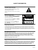
SAFETY INFORMATION Recognize Safety Information This is the safety-alert symbol. When you see this symbol on our machine or in this manual, be alert to the potentially of personal injury. Follow recommended precautions and safe operating practices. Understand Signal Words A signal word - DANGER, WARNING, OR CAUTION is used with the safety-alert symbol. DANGER identifies the most serious hazards. Safety signs with signal word DANGER or WARNING are typically near specific hazards.
THIS PAGE LEFT BLANK INTENTIONALLY 620918702 2
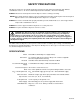
SAFETY PRECAUTIONS This dispenser has been specifically designed to provide protection against personal injury and eliminate contamination of the ice. To ensure continued protection and sanitation , observe the following. ALWAYS: Disconnect electrical power from the dispenser before servicing or cleaning. NEVER: Place hands inside the hopper or gate area without disconnecting electrical power from the dispenser. Agitator rotation occurs automatically when the dispenser is energized.
THIS PAGE LEFT BLANK INTENTIONALLY 620918702 4
INSTALLATION INSTRUCTIONS COUNTER HEIGHT DISPENSER AVAILABLE SPACE USE KIT NO.
FOOT PRINT OF UNIT ON COUNTERTOP 29 – 5/8 COUNTER CUTOUT FOR UNIT DROP IN 27–3/16 25–3/4 FRONT OF COUNTERTOP 31–7/8 THE ABOVE FIGURE SHOWS THE REQUIRED CUTOUT FOR PLACING THE ICE DISPENSER INTO A COUNTERTOP. THE DASHED LINE IS THE ACTUAL CUTOUT DIMENSIONS WHILE THE SOLID LINE SHOWS THE AMOUNT OF OVERHANG FOR THE DISPENSER. FIGURE 1.
7 620918702 FIGURE 2.
THIS PAGE LEFT BLANK INTENTIONALLY 620918702 8
MAINTENANCE The following dispenser maintenance should be performed at the intervals indicated. DAILY (or as required) Remove foreign material from the vending area drip tray to prevent drain blockage. Clean vending area. Check for proper water drainage from the vending area drip tray. MONTHLY Clean and sanitize the hopper interior and the beverage system if applicable (see CLEANING INSTRUCTIONS) ADJUSTMENTS CO2 REGULATORS ADJUSTMENTS WARNING: CO2 displaces oxygen.
1. Remove cover from the dispensing valve by lifting the front cover up 1/4 inch and pulling forward. 2. Install syrup diversion tube assembly on the dispensing valve by pushing rubber end of the syrup diversion tube onto the syrup outlet of the inner nozzle. 3. Measure the water flow rate by dispensing water into a graduated cup for a set period of time. NOTE: Adjusting screw stops are built into the valve to prevent leakage when the screws are adjusted too far clockwise.
2. Install syrup diversion tube assembly on the dispensing valve by pushing the rubber end of the syrup diversion tube onto the syrup outlet of the inner nozzle. Notice: Refer to syrup manufacturer’s recommendations on syrup package for water-to-syrup ratio. 3. Dispense enough to fill syrup diversion tube with syrup. 4. Hold large chamber of the ratio cup under the dispensing valve nozzle. Place free end of the syrup diversion tube into the syrup chamber marked for the proper ratio.
69 67 66 65 77 73 FIGURE 4. AUGER ASSEMBLY CLEANING AND SANITIZING INSTRUCTIONS WARNING: Disconnect electrical power to the dispenser before cleaning. Do not use metal scrapers, sharp objects, or abrasives on the ice storage hopper, top cover, and the agitator disk as damage may result. Do not use solvents or other cleaning agents as they may attack the plastic material. Soap Solution – Use a mixture of mild detergent and warm (100° F) potable water.
C. Wash cup rest with soap solution and rinse with potable water. Install cup rest in drip tray. D. Clean all exterior surfaces of the dispenser with soap solution and rinse with potable water. 2. CLEANING INTERIOR SURFACES CAUTION: When pouring liquid into the hopper, do not exceed the rate of 1/2–gallon per minute. IMPORTANT: Perform the following at least once a month. A. Lift drip tray to expose the hopper, then then remove all ice from the hopper. B.
J. Reassemble the agitator assembly and disc into the hopper. Make certain the retaining screw is tight. K. Using a mechanical spray bottle filled with sanitizing solution, spray the entire interior of the hopper and the agitator assembly. Go to the lower auger drive area and also spray with sanitizing solution. Allow to air dry. L.
11. For post-mix valves, remove the nozzle and syrup diffuser and clean them in a mild soap solution. Rinse with clean water and reassemble the nozzle and syrup diffuser on the valve. 12. For pre-mix valves, disconnect all product tubes from the tank of sanitizing solution and then open the valves to allow the pressure to be relieved. Remove the valves from the dispenser, disassemble and wash thoroughly in a mild soap solution. 13.
620918702 16 FIGURE 7.
FIGURE 8.
THIS PAGE LEFT BLANK INTENTIONALLY 620918702 18
TROUBLESHOOTING IMPORTANT: Only qualified Personnel should service internal components or electrical wiring. WARNING: If repairs are to be made to a syrup system, disconnect syrup supply from the applicable syrup system, then relieve the system pressure before proceeding. If repairs are to be made to the CO2 system, stop dispensing, shut off the CO2 supply, then relieve the system pressure before proceeding.
Trouble AGITATOR TURNS, AUGER DOES NOT TURN (CONT’D) AUGER TURNS, AGITATOR DOES NOT. BEVERAGES DONOT DISPENSE BEVERAGES TOO SWEET. BEVERAGES NOT SWEET ENOUGH BEVERAGES NOT COLD. Probable Cause Remedy C. Inoperative rectifier. C. Replace rectifier. D. Ice jam. D. Clear ice jam. E. Inoperative timer board. E. Replace timer board. A. Inoperative agitator motor. A. Replace agitator motor. B. Inoperative motor capacitor. B. Replace motor capacitor. C. Inoperative timer board. C.
ILLUSTRATED PARTS LIST 92 35 36 103 93 31 82 110 137 16 106 90 112 83 9 117127 4142 80 35 88 109 132 93 114 33 13 35 93 86 33 142 29 94 31 93 52 118 87 53 141 79 133 59 134 31 16 105 36 93 136 78 35 115 116 96 48 89 122 98 85 40 99 34 13 31 93 121 146 24.
107 5 125 63 84 124 47 138 140 35 65 130 95 91 69 20 18 19 97 30 124 95 126 65 36 95 100 35 44 52 70 120 153 157 53 154 95 156 73 151 95 22 111 152 36 145 72 113 102 123 119 25 26 32 95 146 155 158 156 148 147 104 24 160 161 38 7 29 146 39 113 8 1445 620918702 159 22 157 149 157 157 27 37 157 51
81 57 60 43 23 108 56 36 36 61 55 71 35 49 62 36 76 46 64 35 74 50 28 68 67 54 129 66 144 135 23 620918702 15
PR150BC ASSEMBLY Item No. Part No.
PR150BC ASSEMBLY (CONT’D) Item No. Part No. Name 45 90432 Label, Warning, Disconnect 46 90580 Label, Identification Data 47 90629 Label, Clean Hopper 48 91486 Medallion, Cornelius Logo 49 91956 Label, Warning Chiller Disconnect 50 92067 Label, Operation, Agitation Timer 51 92305 Label, Notice Transformer 52 31525003 O-Ring, .239 I.D. By .070 CS 53 31525017 O-Ring, .426 I.D. By .
PR150BC ASSEMBLY (CONT’D) Item No. 87 Part No. 620045724 620045727 Name Base, Tower LH Base, Tower RH 88 620045904 Bracket, Dispense Switch 89 620045958 Bracket Ass’y, Interlock Switch 90 620046005 Cover, Reservoir 91 620046017 Cover, Bin Thermostat 92 620048102 93 70076 Hex Nut, Keps, No. 8-32 94 70188 Screw, Knurled Hd, No. 8-32 95 70204 Screw, Self-Tapping, No.
PR150BC ASSEMBLY (CONT’D) Item No. Part No. Name 132 620704604 133 620708524 Fitting, 3/8 By 1/2 MPT Cup Rest 134 620705201 Pushon Nut, 3/16 135 620705401 Insert Nut, 1/2-13 136 620705501 Retainer, Ice Chute Holddown 137 620708202 Plug 138 620708908 Tube, Bin Stat 139 620709301 Lever, Ice 140 620709601 Clip, Pushon 141 620709604 Clip, Back Lid, Left-Hand 142 620707605 Clip, Back Lid, Right-Hand 143 620709901 Pop Rivet, 125 Dia.
WARRANTY IMI Cornelius Inc. Products Company warrant that all equipment and parts are free from defects in material and workmanship under normal use and service. For a copy of the warranty applicable to your Cornelius product, in your country, please write, fax or telephone the IMI Cornelius office nearest you. Please provide the equipment model number and the date of purchase. Locate the office in your area on the Cornelius web site, www.cornelius.com, under the contacts tab.
IMI CORNELIUS INC. www.cornelius.