
Technical information


Non-Carbonated Impulse Installation & Operations Manual
Publication Number: 859000159INS - 5 - © 2003-2012, IMI Cornelius Inc.
NOTE: Make sure that the electrical power circuit breaker is switched off or the fuse removed.
Before connecting electrical power to the unit, refer to nameplate to verify the power requirements.
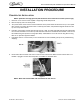
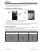
A. Remove the following:
• front merchandiser by removing two screws on the top and lifting up
• key switch wires
• hood by removing two screws on the top and lifting up and forward.
B. Remove second valve from the left to facilitate routing of the new cord.
C. First route the new cord up behind the valve panel and through the cutout in the pump deck. Use the
already attached wire tie/fastener on the deck to secure the cord.
D. Connect cord to the receptacle on the refrigeration deck.
E. Turn the circuit breaker on and then the units power switch. Check to see that the agitator motor has
started. After about three minutes the compressor should start. If the agitator or compressor do not start call
Technical Services.
CONNECT CONCENTRATE AND WATER LINES
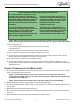
1. Route concentrate and plain water lines from the back side of the unit and under the unit to the front. Connect
them to the appropriate inlet connections.
NOTE: If water supply pressure to the unit is less than 40 psi, a water pressure booster is
required. If water supply pressure to the unit is more than 50 psi, a water pressure regulator must
be installed in the supply line.
NOTE: A water shutoff valve and water filter in the water supply line are recommended.
2. Make the connection behind the splash panel to the marked 3/8 water tubes.
3. Connect optional drip tray drain hose (if used). Be sure the knock-out in the drip pan has been removed if drain
hose is used.
4. Bleed each valve into a bucket until water comes out.
5. Be sure that all concentrate sources are connected and on. Bleed each valve into a bucket until concentrate
comes out.
6. Reinstall drip tray and position water bath overflow hose in drip tray indent.
GLOBAL ICE BANK CONTROL (GIBO) THEORY OF OPERATION
Once electrical power is supplied to the Unit,
the agitator motor will start. There will be a
three-minute time delay before the refrigeration
compressor and the condenser fan motor will
start. This three-minute time delay will take
place each time electrical power to the Unit is
interrupted.
The Unit will continue to operate until ice
covers all three stainless-steel pins on the ice
bank control probe. The ice bank control
module senses this by measuring the
difference in electrical resistance between the
water and the ice. When the ice on the
evaporator coil becomes thick enough, it
covers the three stainless-steel pins on the
ice bank control probe. The control module
senses there is enough ice and turns the
refrigeration compressor and the
condenser fan motor off.
The Unit remains turned off until the ice
bank control three stainless-steel pins are
free of ice. Once this happens, the ice bank
control module starts the refrigeration
compressor and the condenser fan motor.