® INTELLICARB Training Manual Release Date: April 29, 2004 Publication Number: TP01071 Revision Date: NA Revision: A Visit the IMI Cornelius web site at www.cornelius.com for all your Literature needs.
INTELLICARB TRAINING MANUAL The products, technical information, and instructions contained in this manual are subject to change without notice. These instructions are not intended to cover all details or variations of the equipment, nor to provide for every possible contingency in the installation, operation or maintenance of this equipment.
InelliCarb Training Manual TABLE OF CONTENTS Introduction . . . . . . . . . . . . . . . . . . . . . . . . . . . . . . . . . . . . . . . . . . . . . . . . . . . . . . . . . . .1 Unit Description . . . . . . . . . . . . . . . . . . . . . . . . . . . . . . . . . . . . . . . . . . . . . . . . . . . . . .1 Theory of Operation . . . . . . . . . . . . . . . . . . . . . . . . . . . . . . . . . . . . . . . . . . . . . . . . . .1 Description . . . . . . . . . . . . . . . . . . . . . . . . . . . . . . . . . . . . . .
IntelliCarb Training Manual Electrical Section . . . . . . . . . . . . . . . . . . . . . . . . . . . . . . . . . . . . . . . . . . . . . . . . . . . . . 24 Carbonator Wiring Diagram . . . . . . . . . . . . . . . . . . . . . . . . . . . . . . . . . . . . . . . . . . . 25 Wiring Diagram 1xx (120V) . . . . . . . . . . . . . . . . . . . . . . . . . . . . . . . . . . . . . . . . . . . 26 Schematic 1xx . . . . . . . . . . . . . . . . . . . . . . . . . . . . . . . . . . . . . . . . . . . . . . . . . . . . .
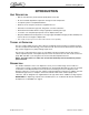
InelliCarb Training Manual INTRODUCTION UNIT DESCRIPTION • Built-in cold carbonator produces bottle-quality drinks every time • No seasonal CO2 adjustments required for changes in water temperature • A complete system for simplified installation • Reduces service frequency and lowers equipment life cost • Generates increased beverage sales and greater consumer satisfaction • Illuminated merchandiser delivers unique, high impact marketing message • Ice used to cool cold plate kept separate from
IntelliCarb Training Manual SPECIFICATIONS Model Descriptions: Ice Storage: Maximum Number of Faucets Available: Built-in Cold Plate: ED150 B=(Beverage) C=(Coldplate) H=(Internal Carb) Z=(No DripTray) 150 Pounds 6 ED175 B=(Beverage) C=(Coldplate) H=(Internal Carb) Z=(No DripTray) 175 Pounds 8 ED200 B=(Beverage) C=(Coldplate) H=(Internal Carb) Z=(No DripTray) 200 Pounds 10 ED250 B=(Beverage) C=(Coldplate) H=(Internal Carb) Z=(No DripTray) 250 Pounds 10 ED300 B=(Beverage) C=(Coldplate) H=(Internal Carb)
InelliCarb Training Manual INSTALLATION 1. Locate the dispenser indoors on a level counter top. A. LEG OPTION Unpack the four (4) legs and install them into the threaded holes provided in the bottom of the unit. The installer must provide flexibility in the product and utility supply to permit shifting the position of the dispenser sufficiently to clean the area beneath it. B. COUNTER MOUNTING If counter mounted the ice drink dispenser must be sealed to the counter.
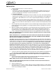
IntelliCarb Training Manual Drains Use a 1 - 1/2” rigid pipe (e.g. ABS on P.V.C.) this is to prevent kinking or collapsing. Make sure to leave a 4 inch air gap between the drain line and the floor drain. CORNELIUS INTELLICARB CARBONATOR ASSEMBLY 1. Ice Drink / Drop-In Carbonator Pump & Motor Unit Vent to Atmosphere Check Valve 125 G.P.H. ProCon Water Pump Liquid Level Control Box Preset CO2 Regulator (75P.S.I.
InelliCarb Training Manual C. Initial start-up procedure for carbonated water system: Turn on the CO2 supply to the carbonator tank, vent air from carbonator tank by pulling the tank relief valve. Turn on water supply to the pump. Connect electrical power to the pump and motor unit. Bleed the air out of the system by energizing a beverage valve until carbonated water is flowing from the valve.
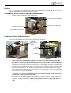
IntelliCarb Training Manual Ice Drink Model ED150/175/300 Coldplate Cover Liquid Level Probe Ice Drink Model ED200/250 Coldplate Cover CO2 Check Valve with Ground Stud In-line CO2 Check Valve 3.
IntelliCarb Training Manual 6. Check list for proper “finished” drink carbonation: A. Fill ice storage hopper with ice. B. Water supply must be from a continuous source (no tank supply). C. Use only filtered water. D. Supply water line to the carbonator pump must be a minimum of .375 ID. E. Syrup supply lines must be a minimum of .265 ID. F. Water inlet pressure range: 45-60 max. static psig. with a minimum flowing pressure of 30 psig. G. Syrup CO2 secondary regulator pressure set to 60 psig. H.
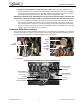
IntelliCarb Training Manual MECHANICAL SECTION GATE RESTRICTOR PLATE NOTE: Disconnect power to dispenser before installing, removing, or adjusting restrictor. ADJUSTMENT INSTALL PLATE ON STUDS AS SHOWN FIGURE 12 Adjustment This plate may be adjusted as shown to reduce or increase the dispensing rate of ice, especially desirable when using glasses or other containers with small openings. Adjustment can be made by sliding up or down with nuts loosened, to obtain the desired amount of restriction.
IntelliCarb Training Manual ICE DIVERTER KIT 02394 NOTE: For dispensing Scotsman, Wilshire, and Hoshizaki compressed ice cubes: 1. 2. 3. 4. 5. 6. 7. Disconnect power to dispenser. Remove Merchandiser from dispenser. Remove ice chute and discard gate restrictor. Install ice diverter on gate mounting plate as shown below. Apply RTV to back surface of ice diverter, to seal to gate mounting plate. Reinstall gasket and ice chute. Reinstall merchandiser and energize unit.
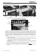
IntelliCarb Training Manual REMOVAL AND REPLACEMENT OF AGITATORS To Remove Agitators For Cleaning (300 shown) NOTE: All other models have only one agitation Assembly. RIGHT HAND AGITATOR WITH HOLE IN UPRIGHT LEFT HAND AGITATOR O–RING COUNTERCLOCKWISE CLOCKWISE ROTATION ROTATION FRONT (VALVE SIDE) VIEW FROM TOP OF DISPENSER FIGURE 14 1. Lift agitator and disc from unit. 2. Remove O-Ring starting at notch. Warm the O-Ring with water to ease removal. 3.
IntelliCarb Training Manual POST-MIX VALVE SECTION SET-UP INSTRUCTIONS Concentrate valve sleeve has only one hole Syrup valve sleeve has six holes FIGURE 15 A side water lever kit can be added to a valve allowing for dispensing of water without syrup or concentrate. The side water lever can be added to either a carbonated drink valve or a noncarbonated drink valve.
IntelliCarb Training Manual NOTE: The notched water piston on the Ultra Flow and UFB-1 valve. results in at least one orifice in the sleeve always open. This eliminates pulsating and smooths water flow at higher flow rates. In operation the liquid flows through the knife–edged orifice in the bottom of the piston and then out the orifices in the sleeve. The outlet orifice size in the sleeve is regulated by the position of the piston.
IntelliCarb Training Manual Adjusting Flow Rates Flow rates of the water and syrup are adjusted based on the desired ratio. For example: if the desired ratio is 5:1, then the flow rate of the water is 5 times that of the syrup. If the desired finished drink total flow rate is 3.0 ounces per second, then the water flow rate is 2.5 oz./ sec and the syrup flow rate is 0.5 oz./sec. (The water at 2.5 oz./sec is five times the 0.5 oz./sec syrup flow rate.) NOTE: Always adjust water within its range.
IntelliCarb Training Manual Setting Ratios If the ratio varies and must be adjusted often, it is probably the result of a restricted syrup system. It is then time to clean and sanitize the syrup tubing and cooling coils and check for other problems such as syrup pumps, etc. NOTE: Try raising the pressure on the pump before cleaning. Set the water flow rate first, then adjust the syrup to the desired ratio. This gives the most accurate valve flow setting possible.
IntelliCarb Training Manual SHURFLO SHURFLOW OVERVIEW SHURflo’s Beverage Gas Pump supplies syrup under pressure to a post-mix dispenser, which mixes the syrup with water to an exact ratio (brix). The pump is used in conjunction with non-pressurized Bag-InBox (B-I-B) containers and a bag connector (Q.D.) fitting. The pump can be operated on regulated CO2, nitrogen or compressed filtered air. The compressed gas drives the pump and is not in contact with the syrup.
IntelliCarb Training Manual SHURFLOW INSTALLATION • As indicated on the pump, the outlet port is to be mounted up. • Pumps are to be mounted at the same level or higher than the B-I-B. The best choice is to have the pump above the B-I-B. • INLET tubing from the B-I-B to the pump use; 3/8" I.D. [10mm] minimum, heavy wall (1/8" [3mm]) clear, NSF listed vacuum tubing. Inlet tubing should not have excessive length.
IntelliCarb Training Manual PLUMBING TYPICAL INSTALLATION FIGURE 21. Typical Installation © 2004, IMI Cornelius Inc.
IntelliCarb Training Manual PLUMBING LAYOUT Brand Syrup Inlets 3-5 Per Side Carb Water In Plain Water In Carbonator Tank CO2 Inlet Brand Syrup Inlets 3-5 Per Side Connection Legend B B B C B 75 psi Fixed Reg Carb Pump B 3/8" Barb Conn C 1/4" Barb Conn D 3/8" Hose Barb - 3/4" NP E 1/4" Female Flr Nut F Direct Conn to SUR Outlet on BIB Pmp G Direct Conn to CO2 Inlet on BIB Pmp H Syr Inlet BIB Pmp I 3/4" NPT TEE CO2 Supply Regulator 100 psi E A 3/8" Female Fir Nut C E A A
FAUCETS W1, VALVES 1,2, 3,6 W1 6 S6 OPTIONAL PRESSURE REGULATOR POTABLE WATER SUPPLY 5 S5 FILTER W2 4 CARBONATOR PUMP S4 COLDPLATE NON-- CARB WATER INSTALL FOR NON-- CARB AS REQUIRED CHECK VALVE S5 INLET S6 CONNECTIONS S7 S1 S2 CARBONATOR TANK FIGURE 23. Flow Diagram 1xx (Six Flavor Model) - 19 - FAUCETS VIEWED FROM THIS SIDE W2, VALVES 4,5 S3 W2 3 5-- 15 PSIG OPTIONAL FOR DIET DRINKS OR ROOT BEER PLUGGED S3 FLOW DIAGRAM 1XX (SIX FLAVOR MODEL) © 2004, IMI Cornelius Inc.
S8 W1 OPTIONAL PRESSURE REGULATOR 7 POTABLE WATER SUPPLY S7 FILTER 6 W2 5 CARBONATOR PUMP W2, VALVES 4, 5,6 S5 NON-- CARB WATER CHECK VALVE INSTALL FOR NON-- CARB AS REQUIRED S5 S6 COLDPLATE INLET CONNECTIONS S7 S8 S1 S2 CARBONATOR TANK FAUCETS VIEWED FROM THIS SIDE - 20 - FIGURE 24. Flow Diagram 1XX (Eight Flavor Models) S6 S3 S4 4 S4 W2 5-- 15 PSIG OPTIONAL FOR DIET DRINKS OR ROOT BEER 3 75 PSI S3 2 S2 S4 W1 1 © 2004, IMI Cornelius Inc.
8 W1 OPTIONAL PRESSURE REGULATOR W1 VALVES 1,2 3,6,7,8 POTABLE 7 WATER SUPPLY FILTER W2 VALVES 4,5 CARBONATOR INSTALL FOR 6 NON–CARB AS REQUIRED W2 CHECK VALVE S8 Non–Carb Water S7 S6 COLDPLATE INLET CONNECTIONS S5 W2 W1 S4 CARBONATOR TANK - 21 - FIGURE 25. Flow Diagram 2xx (Eight Flavor Models) 5 S3 S2 S1 4 OPTIONAL FOR DIET DRINKS OR ROOT BEER W2 75 PSI 5–15 PSIG 3 FLOW DIAGRAM 2XX (EIGHT FLAVOR MODELS) © 2004, IMI Cornelius Inc.
Publication Number: TP01071 - 22 - 1 2 3 4 5 CARBONATOR TANK S1 S2 S3 S4 S5 S6 S7 S8 S9 S10 COLD PLATE W1 W2 W2 W1 ITEMS INSIDE BROKEN LINE INCLUDED WITH UNIT COLDPLATE INLET CONNECTIONS 6 7 8 9 10 FAUCETS S1 S2 S3 S4 S5 S6 S7 S8 S9 S10 OPTIONAL FOR DIET DRINKS OR ROOT BEER 5–15 PSIG W2 VALVES 5,6 W1 VALVES 1,2,3 4,7,8,9,10 S1 S2 S3 S5 SYRUP TANKS 15–50 PSIG S4 S6 S7 CARBONATOR PUMP NON CARB WATER DOUBLE CHECK VALVE S8 CHECK VALVE S9 75 PSI CO2 CYLINDE
12 DOUBLE CHECK VALVE COLD PLATE W1 S12 OPTIONAL PRESSURE REGULATOR 11 S11 W2 FILTER 10 S10 COLDPLATE INLET CONNECTIONS FAUCETS VIEWED FROM THIS SIDE - 23 - FIGURE 27.
IntelliCarb Training Manual ELECTRICAL SECTION Control Box Single Transformer Will Power up to Three Valves Simultaneously. Transformer FIGURE 28. Electrical Box 1xx Single Transformer FIGURE 29. Electrical Box 2xx Single Transformer One Transformer Powers the Left Bank and the Other Powers the Right Bank. Will Power All Valves Simultaneously. Transformers FIGURE 30. Electrical Box 2XX Dual Transformer Publication Number: TP01071 - 24 - © 2004, IMI Cornelius Inc.
IntelliCarb Training Manual RESET CONNECTIONS Time Out Selection Pins. 7min/3 min/Disabled (Move Jumper to Select) CARBONATOR WIRING DIAGRAM © 2004, IMI Cornelius Inc.
TO HINGE DA NG ER! MOTOR HEATER CCW AGITATOR MOTOR GRN TO BEVERAGE FAUCET DISPENSE SWITCH Q.C. CONNECTOR GATE SOLENOID (106VDC) N L WG HR I E T E E N WO BRB BBR BB HR L L L I A AE AE L UL AL U NC DA T C CCD E E EG EK K K K + B L A C K B L U E -- - 26 - FIGURE 31. Wiring Diagram 1xx (120V) GRD 115V SUPPLY EL ECTRIC SHO CK HA ZA RD. DISCO NNECT PO W ER B EFO RE SERVICING UNIT.
IntelliCarb Training Manual SCHEMATIC 1XX G N L TIMER L2 L1 MO TO R H EATER A G ITATO R MO TO R N .O . C VEN D SW ITC H N .C . C A PA C ITO R R EC TIFIER G ATE SO L EN O ID O PTIO N A L B A L L A ST O PTIO N A L L IG H T O PTIO N A L STA R TER B EVER A G E TR A N SFO R MER O PTIO N A L L O W IC E L EVEL T’STAT B EVER A G E VA LVES L IG H T B EVER A G E VA LVES B EVER A G E PA N EL FIGURE 32. Schematic 1xx © 2004, IMI Cornelius Inc.
Q.C. CONNECTOR GRN TO HINGE GATE SOLENOID (106VDC) DANGER! ELECTRIC SHOCK HAZARD. DISCONNECT POWER BEFORE SERVICING UNIT. BLUE ICELEVELSIGNAL OPTION KEY SWITCH + B L A C K WB H L I U T E E BLACK WHITE © 2004, IMI Cornelius Inc.
© 2004, IMI Cornelius Inc.
IntelliCarb Training Manual WIRING DIAGRAM 2XX (220/240V MODELS) G L N L1 TIMER L2 RECTIFIER MOTOR HEATER AGITATOR MOTOR N.O. C VEND SWITCH N.C. GATE SOLENOID OPTIONAL BALLAST OPTIONAL LIGHT OPTIONAL STARTER OPTIONAL BEVERAGE TRANSFORMER OPTIONAL ICE LEVEL OPTIONAL BEVERAGE VALVES OPTIONAL BEVERAGE VALVES BEVERAGE PANEL FIGURE 35. Wiring Diagram 2xx (220/240V Models) Publication Number: TP01071 - 30 - © 2004, IMI Cornelius Inc.
N L © 2004, IMI Cornelius Inc.
Publication Number: TP01071 N L OPTIONAL LIGHT SOCKET G B B R R L E N U E N GRN LEFT AGITATOR MOTOR (CCW) B L A C K - 32 - BLACK BLACK WO H R I N T E B L U E G R E E N R E D B L U E OPTIONAL LIGHT STARTER B L U E GRN BLACK GATE SOLENOID (DC COIL) BRN MOTOR CAPACITOR TO HINGE BLUE RED OPTIONAL LIGHT BALLAST WHITE LIGHT BLUE TO 24V TRANSFORMER B L U E 2 G R E E N PINK ICE LEVEL SIGNAL OPTION 1 T’STAT BLUE B L A C K B L A C K YELLOW TO BEVERAGE FAUCET KEY SWITCH (OPTIO
IntelliCarb Training Manual SCHEMATIC 300 (120V MODELS) G L N TIMER L1 L2 RECTIFIER MOTOR HEATER AGITATOR MOTOR N.O.1 C VEND SWITCH N.C.1 CAPACITOR GATE SOLENOID BALLAST OPTIONAL LIGHT STARTER OPTIONAL BEVERAGE TRANSFORMER OPTIONAL ICE LEVEL OPTIONAL BEVERAGE VALVES BEVERAGE PANEL MOTOR HEATER AGITATOR MOTOR N.O.2 C VEND SWITCH N.C.
IntelliCarb Training Manual SCHEMATIC 300 (220/240V MODELS) G N L EMC LINE FILTER E–BOX GD. MOTOR HEATER MOTOR HEATER TIMER L1 L2 RECTIFIER GATE SOLENOID POWER PUSH BUTTON SWITCH N.C1 C VEND SWITCH N.O1 OPTIONAL BALLAST AGITATOR MOTOR OPTIONAL LIGHT OPTIONAL STARTER OPTIONAL BEV. TRANSFORMER BEVERAGE KEYLOCK SWITCH 24V BEV. FAUCETS EMC GATE SOLENOID N.C2 C VEND SWITCH N.O2 OPTIONAL BALLAST AGITATOR MOTOR OPTIONAL LIGHT OPTIONAL STARTER OPTIONAL BEV. TRANSFORMER 24V BEV.
IntelliCarb Training Manual TROUBLESHOOTING SHURFLOW TROUBLESHOOTING Pumping Capability The distance syrup can be delivered is limited by inherent factors (restrictions) within the inlet & outlet sides of the beverage dispensing system. Due to variances in system configuration and equipment, an accurate determination of pressure drop is difficult.
IntelliCarb Training Manual The chart indicates that heavy syrup with 1/2 oz./sec [15mL] flow-rate (per the illustration) can be sustained over a horizontal distance of 500 ft. [152M] when 3/8" I.D. [10mm] tubing is used. Feet: Take 1% of 500 ft. (500 x 1%) = 5. Which then is multiplied by the 22 ft. vertical, (22 x 5) = 110 ft. Subtract this product from the 500 ft. (500 - 110) =390. The results indicate a 390 ft. tubing run (horz./vert.) is possible, while the example only requires a distance of 370 ft.
IntelliCarb Training Manual Pump Troubleshooting DOES NOT OPERATE / GAS APPLIED / DISPENSER VALVE OPEN • B-I-B empty or inlet tubing pinched off activating vacuum "sold-out". • Gas regulator over-pressurizing. (Pump stalled) • Outlet tube kinked or restricted. • Operated without fluid for excessive period. (Dry run) • Transfer tube and gas lines contaminated (syrup, rust, oil, etc.) [ensure clean gas supply, change out all contaminated pumps] • Internal damage of control cover.
IntelliCarb Training Manual DISPENSER TROUBLESHOOTING Should your unit fail to operate properly, check that there is power to the unit and that the hopper contains ice. If the unit does not dispense, check the following chart under the appropriate symptoms to aid in locating the defect. Trouble BLOWN FUSE OR CIRCUIT BREAKER. GATE DOES NOT OPEN. AGITATOR DOES NOT TURN. GATE DOES NOT OPEN OR IS SLUGGISH. AGITATOR TURNS. ICE DISPENSES CONTINUOUSLY. SLUSHY ICE. WATER IN HOPPER.
IntelliCarb Training Manual VALVE TROUBLESHOOTING Excess Foam Excess Foam Problem: excess foam Check product temperature Temp ? Check system above 40° below 40° Remove nozzle Clean ? yes Check flow rates no Correct ? Clean yes Check system no Problem corrected Set flow rate and ratio Problem corrected © 2004, IMI Cornelius Inc.
IntelliCarb Training Manual Off Taste Off Taste Problem: off taste Remove nozzle Clean ? yes Check ratio no Clean Correct ? yes Check system no Problem corrected Set ratio Problem corrected Publication Number: TP01071 - 40 - © 2004, IMI Cornelius Inc.
IntelliCarb Training Manual Valve Stuck Open Valve Stuck Open Problem: valve stuck open Check solenoid visually working ? yes (solenoid up) Check for damaged banjos no (solenoid down) Damage ? Check for power at solenoid Power ? no Undetermined problem call 800-238-3600 yes yes Replace dispensing switch Replace banjos Problem corrected Problem corrected no Clean or replace solenoid Problem corrected © 2004, IMI Cornelius Inc.
IntelliCarb Training Manual No Product No Product Problem: no product Check solenoid visually yes Check system Check voltage (22-27 AC) no Check transformer Power ? yes Check resistance of coil Working ? no no Replace switch no yes Check switch 40 ohms ? yes Check system no Problem corrected Replace solenoid Problem corrected Publication Number: TP01071 - 42 - © 2004, IMI Cornelius Inc.
IntelliCarb Training Manual CARBONATOR TROUBLESHOOTING WARNING: Disconnect electrical power to the unit to prevent personal injury before attempting any internal maintenance. Only qualified personnel should service the internal components or the electrical wiring. If repairs to the carbonated water or the plain water systems must be made, disconnect electrical power to the Unit, then shut off CO2 and plain water sources. Dispense from dispensing valve until carbonator tank CO2 pressure has been relieved.
IMI Cornelius Inc. www.cornelius.