® COUNTERTOP ICEMAKER IMD Series Installation Manual Release Date: April 8, 2004 Publication Number: 638085277INS Revision Date: February 16, 2009 Revision: C Visit the IMI Cornelius web site at www.cornelius.com for all your Literature needs.
COUNTERTOP ICEMAKER IMD SERIES INSTALLATION MANUAL The products, technical information, and instructions contained in this manual are subject to change without notice. These instructions are not intended to cover all details or variations of the equipment, nor to provide for every possible contingency in the installation, operation or maintenance of this equipment.
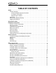
TABLE OF CONTENTS Safety . . . . . . . . . . . . . . . . . . . . . . . . . . . . . . . . . . . . . . . . . . . . . . . . . . . . . . . . . . . . . . . Safety Instructions . . . . . . . . . . . . . . . . . . . . . . . . . . . . . . . . . . . . . . . . . . . . . . . . . . . Read and Follow all Safety Instructions . . . . . . . . . . . . . . . . . . . . . . . . . . . . . . . Recognize Safety Alerts . . . . . . . . . . . . . . . . . . . . . . . . . . . . . . . . . . . . . . . . . . . Different Types of Alerts .
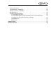
Electrical Checkout . . . . . . . . . . . . . . . . . . . . . . . . . . . . . . . . . . . . . . . . . . . . . . . . . Overload Check - FIGURE 10 . . . . . . . . . . . . . . . . . . . . . . . . . . . . . . . . . . . . . . . . . Compressor Check - FIGURE 11 . . . . . . . . . . . . . . . . . . . . . . . . . . . . . . . . . . . . . . Capacitor Check . . . . . . . . . . . . . . . . . . . . . . . . . . . . . . . . . . . . . . . . . . . . . . . . . . . Troubleshooting Gear Motors . . . . . . . . . . . . . . . . .
Countertop Icemaker IMD Series Installation Manual SAFETY SAFETY INSTRUCTIONS Read and Follow all Safety Instructions Read and follow all safety instructions in this manual and on the machine (decals, labels, and laminated cards). Read and understand all applicable OSHA (Occupation Safety and Health Administration) safety regulations before operating the machine. Recognize Safety Alerts This is the safety alert symbol.
Countertop Icemaker IMD Series Installation Manual SPECIFICATION CHART Models IMD300-15A IMD302-15A IMD300-30A IMD300-30W IMD301-30A IMD301-30W IMD302-30A IMD302-30W IMD600-30A IMD600-30A IMD601-30A IMD601-30W IMD602-30W IMD600-90A IMD600-90W IMD601-90A IMD601-90W IMD602-90A IMD602-90W Condensing Unit Air Cooled Air Cooled Air Cooled Water Cooled Air Cooled Water Cooled Air Cooled Water Cooled Air Cooled Water Cooled Air Cooled Water Cooled Water Cooled Air Cooled Water Cooled Air Cooled Water Cooled Air
Countertop Icemaker IMD Series Installation Manual S HIP P ING WT. (IMD300-- 30) 220 L B S . (A P P R OX.) S HIP P ING WT. (IMD600-- 30) 240 L B S . (A P P R OX.) FIGURE 2. DIMENSION DRAWINGS (30 LBS.) IMD 300-30 AND IMD 600-30 S HIP P ING WT. 225 L B S . (A P P R OX.) FIGURE 3. DIMENSION DRAWINGS (90 LBS.) IMD600-90 © 2004-2009, IMI Cornelius Inc.
Countertop Icemaker IMD Series Installation Manual INSTALLATION INSTRUCTIONS REMOVE ICEMAKER FROM CARTON 1. 2. Keep unit in the upright position, remove carton and pallet from unit and inspect unit for damage. Upon inspection of unit, if any damage is found, file a claim with carrier immediately. Locate Startup Card either on outside of container or on plastic liner. Fill in proper information and send one copy to factory, and other copy to Distributor. Postage is prepaid. CABINET REMOVAL 1. 2. 3. 4. 5.
Countertop Icemaker IMD Series Installation Manual DRAIN CONNECTION 1. 2. 3. 4. 5. 6. Install splash panel on machine and hold in place with (2) screws. Do not tighten at this time. Remove drain tray mounting bracket from their shipping carton. Clip the drain try mounting bracket onto the bottom of the splash panel in the brackets provided. Hook the drain tray into the splash panel and onto the mounting bracket. Push the drain elbow securely onto the drain tray. Do not glue in place.
Countertop Icemaker IMD Series Installation Manual Low Water Safety Control - Adjust magnet by bending magnet arm as shown in FIGURE 4 to shut down unit if the water level drops below the line on the side of the reservoir. Bin Control - Remove four screws from top of bin cover and lift cover so bin control plate can be manually lifted until unit shuts down.
Countertop Icemaker IMD Series Installation Manual GUIDE TO SERVICE ICEMAKER CLEANING AND SANITIZING PROCEDURES Do not use any of the ice made during cleaning operations. Clean and sanitize ice storage area when cleaning icemaker. 1. 2. 3. 4. 5. 6. 7. 8. 9. Turn machine off. Shut off water supply. Remove ice from storage bin. Mix approved cleaner (2 gallons as directed). Recommended cleaner: Calgon Corp. of Virginia Chemicals, ice machine cleaner. Mixture: 3-1/3 ounces per gallon of water.
Countertop Icemaker IMD Series Installation Manual SEMI-ANNUALLY Semi-Annually in addition to all previously established service procedures perform the following: 1. 2. 3. 4. 5. 6. 7. Check for water leaks in tube connections, water fittings, and lower icemaker water seal. Check drain tubes for clogs and “aged” tubes. Replace if tubes are stained or brittle. Check for signs of condensation. Clean where necessary and replace insulation properly. Check safety circuits for proper operation.
Countertop Icemaker IMD Series Installation Manual WATER LEVEL CONTROL HOW WATER LEVEL CONTROL WORKS When water is introduced through the inlet fitting the float rises. The float pushes against a lever which in turn forces the poppet assembly against the inlet fitting valve seat which seals the water off, (see FIGURE 4). Before the water inlet is sealed the safety switch is operated. In the event of a water failure the float would drop down and operate the safety switch to shut off the machine.
Countertop Icemaker IMD Series Installation Manual The operating positions of the switch are fixed, no adjustments are necessary. If switch replacement becomes necessary, simply disconnect cable at connector, remove wires from switch. Temperature/Pressure Charts* Air Temperature 10 lbs.
Countertop Icemaker IMD Series Installation Manual NOTE: On water cooled units adjust condenser modulating valve before troubleshooting expansion valve. CAUTION: Very high discharge pressure is present in system. Quick disconnects on your gages will minimize Danger and loss of refrigerant. Comply with federal regulations for reclaiming refrigerant.
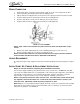
Countertop Icemaker IMD Series Installation Manual GEAR MOTOR The gear motor is equipped with a start relay and a manual reset overload. When current is applied, the relay energizes and completes the circuit to the start winding. The motor reaches a predetermined speed and the relay drops out, disconnecting the start winding. The run winding remains in the circuit as long as current is applied.
Countertop Icemaker IMD Series Installation Manual AUGER & EXTRUDING HEAD REMOVAL 1. 2. 3. 4. 5. Disconnect unit from power supply. Remove storage container cover and put aside. Turn off water supply to icemaker. After ice has melted from head take hold of the auger nut and lift straight up to disengage from icemaker. When replacing the auger assembly, make certain that both the auger engages the output shaft drive and the extruding head ribs engage the evaporator tube collar. See FIGURE 8. FIGURE 9.
Countertop Icemaker IMD Series Installation Manual TO REPLACE BEARINGS 1. 2. 3. 4. 5. 6. 7. Dispense all ice from unit. Disconnect unit from electrical power. Remove panels. Unplug Dispense Motor and Ice Level Switch. Remove four screws holding dispense cover in place. Remove dispense cover assembly. Use an open end wrench on auger nut connected to bearing and turn and turn counterclockwise to remove assembly. 8. Remove worn bearings. Replace with new bearings and then reinstall assembly.
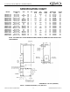
Countertop Icemaker IMD Series Installation Manual OVERLOAD CHECK - FIGURE 10 4. Using a volt-ohm meter check the continuity across the overload, contacts #1 & #3. If none, wait for unit to cool down and try again. If still no continuity, the overload protector is defective and should be replaced. COMPRESSOR CHECK - FIGURE 11 The resistance readings on the windings will be between 0.25 and 10.00 ohms, a meter capable of these low readings must be used. 5. 6. 7. 8. Check between “C” & “R”.
Countertop Icemaker IMD Series Installation Manual Motor Check The resistance readings on the windings will be between 5 to 25 ohms. A meter capable of these low readings must be used. The Start Relay cover must be removed. If no continuity on start or run winding test, replace stator. If continuity on grounded motor test, replace stator. FIGURE 12. PIN NUMBERS Publication Number: 638085277INS - 16 - © 2004-2009, IMI Cornelius Inc.
Countertop Icemaker IMD Series Installation Manual SAFETY CONTROLS Your Icemaker unit has several safety and control devices incorporated into its design. WARNING: None of the below described devices should ever be “bypassed” to allow the unit to function. The safety and control system shut-off devices are: FIGURE 13. 1. 2. 3. 4. 5. 6. Low water shut off reed switch located in icemaker float assembly. (Automatic reset type). Gear motor thermal overload, manual reset type (red button on motor).
Countertop Icemaker IMD Series Installation Manual GUIDE TO GOOD ICE CUSTOMER COMMENTS “It runs but the ice is too soft.” “The icemaker is not producing enough ice.” CHECK ICEMAKER LOCATION CONDITIONS FIRST • Proper air flow for condensing system. • Location too close to high units such as coffee urns, deep fryers, grills, etc. • Supply water conditions Water too warm (above 90oF. “The ice is too wet.” Water artificially softened above 262 ppm sodium chloride.
© 2004-2009, IMI Cornelius Inc. Too much refrigerant in system. Evacuate and recharge system. Clean condenser. Non-condensible in system. Check electrical wiring in con trol box for loose connec tions. Check for failed service switch or relay. Check power to machine. NO POWER - 19 Plugged liquid line dryer. Replace dryer. Evacuate and recharge system. Check for leaks. Condenser dirty or restricted. Low on refrigerant. Check electrical circuit to fan motor. Check fan motor.
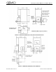
Countertop Icemaker IMD Series Installation Manual BLK 1 2 ICE SELECT BRN LIGHT WHT YLW 4 1 DISP. SWITCH WHT 2 LIGHT WATER SELECT BRN BLK YLW DISPENSE MOTOR WHT YLW BLK YLW BRN BLK RED BLU WHT ORG YLW BRN GRN BRN GRN GRY 3 BRN ORG BLU WATER VALVE DRINK FRONT OPTION 1 WHT BLK 5 RED 1 3 4 SERVICE SWITCH BLK BLK WHT BLK BLK GRN 6 WHT WHT 2 ANTI-FREEZE RELAY WHT ELECTRICAL BOX 2 3 LOW WATER ICE LEVEL FAN COMP.
Countertop Icemaker IMD Series Installation Manual FIGURE 15. SCHEMATIC IMD 300-30, IMD 600-30, IMD 601-30, IMD 600-90, AND IMD 601-90 © 2004-2009, IMI Cornelius Inc.
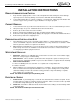
Countertop Icemaker IMD Series Installation Manual FIGURE 16. SCHEMATIC IMD 302-30, IMD 602-30, AND IMD 602-90 Publication Number: 638085277INS - 22 - © 2004-2009, IMI Cornelius Inc.
IMI Cornelius Inc. www.cornelius.