® IDC 255 PROGATE DRIVE THRU Service Manual Release Date: June 27, 2006 Publication Number: 621057419SER Revision Date: NA Revision: A Visit the IMI Cornelius web site at www.cornelius.com for all your Literature needs.
IDC 255 PROGATE DRIVE THRU SERVICE MANUAL The products, technical information, and instructions contained in this manual are subject to change without notice. These instructions are not intended to cover all details or variations of the equipment, nor to provide for every possible contingency in the installation, operation or maintenance of this equipment.
TABLE OF CONTENTS Safety Instructions . . . . . . . . . . . . . . . . . . . . . . . . . . . . . . . . . . . . . . . . . . . . . . . . . . . . Read and Follow all Safety Instructions . . . . . . . . . . . . . . . . . . . . . . . . . . . . . . . . . . Recognize Safety Alerts . . . . . . . . . . . . . . . . . . . . . . . . . . . . . . . . . . . . . . . . . . . Different Types of Alerts . . . . . . . . . . . . . . . . . . . . . . . . . . . . . . . . . . . . . . . . . . . Safety Tips . . . . . . . . . . . . . .
Yearly . . . . . . . . . . . . . . . . . . . . . . . . . . . . . . . . . . . . . . . . . . . . . . . . . . . . . . . . . . . 17 Water Pump Maintenance (or after water system disruption) . . . . . . . . . . . . . . 17 Cleaning CO2 Gas Check Valve . . . . . . . . . . . . . . . . . . . . . . . . . . . . . . . . . . . . 17 Service . . . . . . . . . . . . . . . . . . . . . . . . . . . . . . . . . . . . . . . . . . . . . . . . . . . . . . . . . . . . . Merchandiser Removal . . . . . . . . . . . . . . . . . . . .
IDC 255 Progate Drive Thru Service Manual SAFETY INSTRUCTIONS READ AND FOLLOW ALL SAFETY INSTRUCTIONS Read and follow all safety instructions in this manual and on the machine (decals, labels, and laminated cards). Read and understand all applicable OSHA (Occupation Safety and Health Administration) safety regulations before operating the machine. Recognize Safety Alerts This is the safety alert symbol.
IDC 255 Progate Drive Thru Service Manual UNIT SPECIFICATION DESCRIPTION The Ice Drink Cornelius (IDC) series of dispensers solves your ice and beverage service needs in a sanitary, space saving, economical way. Designed to be manually filled with ice from any remote ice– making source, these dispensers will dispense cubes (up to 1–1/4 inch in size), cubelets, and compressed (not flaked).
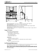
IDC 255 Progate Drive Thru Service Manual 36.901 39.750 PCX OUT OF RATIO LABEL 20.756 CORNELIUS LOGO UNIT SERIAL NUMBER 30.000 FIGURE 1 Electrical Connections: 6 ft long power cord with 3-prong plug attached to dispenser. Power Requirements: 9.3 amps at 120 volts dedicated power supply. Water Supply Requirements: 100 psi (7 bar) maximum static pressure 40 psi (28 bar) minimum dynamic pressure. 3/8” minimum water line recommended. CO2 Requirements: 100 psi max to unit regulated to 35 psi (2.
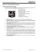
IDC 255 Progate Drive Thru Service Manual PROGATE 2 CONTROL BOX OPERATION Portion Control Box Functions The portion control box on the PROGATE 2 has several functions including dispensing 4 programmed ice portions for 4 cup sizes, programming and a manual dispense mode. 1 2 1. MAIN POWER ON/OFF 3 6 2. AGITATOR PUSH ON 3. MODE SWITCH MANUAL/PROGATE 4. PROGRAM BUTTON 7 4 5. ICE PORTION DISPENSE BUTTONS 5 6. ICE PORTION BAR 7. PROGATE ON LIGHT 8. PORTION SIZE UP/DOWN KEYS 8 1. 2. 3. 4. 5. 6. 7. 8.
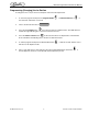
IDC 255 Progate Drive Thru Service Manual Programming (Changing) the Ice Portion To change the size of any of the four ice dispense sizes follow the steps below. 1. To enter the program mode press the Program Button the same time and hold for 5 seconds. 2. The Ice Portion Bar will come on 3. Press the UP ARROW button to increase the amount of dispensed ice. The LED will move towards the right indicating the Ice Portion has been increased. 4.
IDC 255 Progate Drive Thru Service Manual Agitation Time The software coding for the progate system involves a direct relationship between the dispense time and the agitation time.
IDC 255 Progate Drive Thru Service Manual The agitation time equals the dispense time multiplied by the agitation ratio. The user is given the flexibility to change the agitation ratio thereby altering the agitation time in order to ensure that the ice chute is always filled with ice for all the different ice types. 2 10 12 14 16 18 20 22 24 26 28 FIGURE 2 Programming (Changing) the Agitation Time 1. Simultaneously Press and hold for 3 seconds, the 2. buttons to enter the programming mode.
IDC 255 Progate Drive Thru Service Manual Ice Portion Bar The portion bar is used to determine the amount of time programmed for each size button. Each button has a minimum and maximum amount of time that can be programmed. If a button cannot be adjusted to the size desired use another button to get the desired results. =20mS “S” Small 50mS 230mS 80mS 260mS 150mS 330mS 230mS 410mS “M” Medium “L” Large “XL” XLarge FIGURE 3 Publication Number: 621057419SER -8- © 2006, IMI Cornelius Inc.
W2 1 W4 2 3 2 4 5 3 6 4 -9S1 W3 CW NOTES: PLUMBING TO FITTINGS OF DIFFERENT DIAMETER MAY BE ACCOMPLISHED BY SPLICING THE TUBE AND USING APPROPRIATE CONNECTORS W1 CW 1 PW TO PROGATE SYSTEM S2 W2 PW SYRUP 1 OUT (SINGLE TOWER) 6 S3 5 4 S6 S7 9 6 PW COLDPLATE 2 1 12 11 10 S4 S5 3 5 7 8 S8 7 INCLUDED WITH UNIT ELECTRICAL-BOX S9 7 CW S10 8 8 9 10 9 11 W4 PW W3 PRIMARY REGULATOR 110 PSIG SECONDARY REGULATOR 60 PSIG FOR SYRUP BIBS 12 10 CW RECIRC IN W2 PW
- 10 NOTES: PLUMBING TO FITTINGS OF DIFFERENT DIAMETER MAY BE ACCOMPLISHED BY SPLICING THE TUBE AND USING APPROPRIATE CONNECTORS W1 W2 CW 1 1 W4 2 RECIRC IN 3 2 4 5 3 6 4 S1 W3 PW TO PROGATE SYSTEM CW REG A&W OUT (SINGLE TOWER) S2 W2 PW 6 S3 5 4 S6 9 S7 COLDPLATE 2 1 12 11 10 S4 S5 3 8 S8 7 CW INCLUDED WITH UNIT 5 ELECTRICAL-BOX 7 8 9 6 10 11 7 12 W4 8 PW W3 PRIMARY REGULATOR 110 PSIG SECONDARY REGULATOR 60 PSIG FOR SYRUP BIBS REG A&W OUT DUAL TOWER CW SYR
IDC 255 Progate Drive Thru Service Manual E – BOARD OFF CYCLE AGITATION ADJUSTMENTS When Ice is not being dispensed from the machine such as during off hours it is essential to move or agitate the ice to keep it from clumping and to replenish the ice in the cold plate. The amount of time the agitator runs and the time between the agitation cycles can be adjusted depending on ice type or application. The settings for this function are located on the E-Board found in the E-BOX.
BLK 1 3 5 7 BLUE BLK KEY SWITCH SW2 (100 VA) T1 LEFT TOTAL FLEX SOLENOID BLOCK RIGHT TOTAL FLEX SOLENOID BLOCK - 12 - BLK CR3 3 4 P1-3 BLK 0 1 CR3 8 6 CR2 BLK YLW CR3 1 0 OFF CYCLE AGITION MOTOR BY PASS P1-1 ENABLE/DISABLE 3 AUTO/MANUAL MODE SWITCH SW1 2 CR1 4 P1-2 2 25 VAC SECONDARY 120 VAC PRIMARY 18AWG WHT P1-4 18AWG BLK LINE VOLTAGE 120VAC 50/60 HZ YLW18AWG ICE CHUTE COVER SWITCH S2 YLW CR1 BLK YLW 1 0 (50 VA) RED P1-3 BLK 1 BLUE Publication Number: 621057419
© 2006, IMI Cornelius Inc. AIR INPUT - 13 RETRACT P/N 70959 TSN NUTS 6 PLCS PUR YEL BLK BLK YLW YLW BLK 0 CR1 1 8 2 6 4 P1 0 CR2 1 BLK 8 2 6 4 CAPACITOR AGITATOR L2 YLW NO/NC RELAY 0 BLK 1 YLW J2 3 BLK P/N 620052685 CONTROL BOX BRACKET P/Ns: 07052009 - SCREW 0720603-NUT J5 7 CR3 RED AGITATOR EARTH 2 4 RED TRANSFORMER BLU EARTH IN 6 8 P/N 620314825 TIMER BOARD P/N 60569001 RELAY NO 2 PLCS P/N 30774 CAPAC MOTOR AGIT P/N 325192000 BUSHING 1.
AIR INPUT Publication Number: 621057419SER 0 BLK WHT YLW BLK PUR - 14 11 24 12 25 P/N 620314765 SW3 4 1 J1 PB1 8 3 3 P1 P1 X1 2 6 4 INTERFACE BOARD 4 X2 0 CR1 1 BLK MODE SW P/N 32229 HARNESS ASSY.
IDC 255 Progate Drive Thru Service Manual MAINTENANCE The following dispenser maintenance should be performed at the intervals indicated: DAILY (OR AS REQUIRED) Remove foreign material from vending area drip tray to prevent drain blockage. Clean vending area. Check for proper water drainage from the vending area drip tray. Checking CO2 Supply Make sure CO2 cylinder regulator assembly 1800-psi gage indicator is not in shaded (“change CO2 cylinder”) portion of the dial.
IDC 255 Progate Drive Thru Service Manual 4. Return the inner nozzle to the nozzle and replace the assembly to the valve. SNAP FIT CLIP BOTTOM PLATE P/N 1903 SNAP FIT CLIP SNAP FIT CLIP REAR TAB SNAP FIT CLIP O F F INNER NOZZLE NOZZLE MONTHLY Clean and sanitize the hopper interior and beverage system, if applicable (see CLEANING INSTRUCTIONS).
IDC 255 Progate Drive Thru Service Manual 4. 5. 6. 7. 8. 9. Using a plastic pail, prepare approximately five (5) gallons of sanitizing solution. Rinse the B–I–B disconnects in the sanitizing solution. Sanitizing fittings must be attached to each B–I–B disconnect. If these fittings are not available, the fittings from empty B–I–B bags can be cut from the bags and used. These fittings open the disconnect so the sanitizing solution can be drawn through the disconnect.
IDC 255 Progate Drive Thru Service Manual SERVICE MERCHANDISER REMOVAL 1. Remove all lid holders and straw dispenser. FIGURE 8 FIGURE 9 2. Remove screws holding merchandiser to control box. 3. Grab panel by sides, lift up to disengage locking tabs and rotate forward past. FIGURE 10 FIGURE 11 Publication Number: 621057419SER FIGURE 12 - 18 - © 2006, IMI Cornelius Inc.
IDC 255 Progate Drive Thru Service Manual CONTROL BOX REMOVAL 1. With cover removed locate and remove 4 screws from Control box flange. FIGURE 13 2. Pull box forward exposing control board, wiring and switches. FIGURE 14 MAIN ELECTRICAL BOX ACCESS 1. Remove screw-locking cover to electrical box. FIGURE 15 2. Lift cover up and then rotate forward. FIGURE 16 © 2006, IMI Cornelius Inc.
IDC 255 Progate Drive Thru Service Manual ICE CHUTE REMOVAL 1. Remove 4 nuts attaching ice chute to hopper. FIGURE 17 2. Disconnect ice chute switch harness located behind the control box. FIGURE 18 FIGURE 19 3. Pull assembly away form hopper. Do not loose or damage gasket. If damaged or missing replace. 4. Pull ice chute assembly out of splash panel and disconnect the CO2 lines. NOTE: Mark the CO2 lines to avoid improper assembly. FIGURE 20 5.
IDC 255 Progate Drive Thru Service Manual MOTOR REMOVAL Heater, Agitation Motor, & Gear Box NOTE: Apply anti seizing lubricant to the threads of mounting bolts when service is required. Heater Spring Motor Mounting Screws FIGURE 22 © 2006, IMI Cornelius Inc.
IDC 255 Progate Drive Thru Service Manual TROUBLESHOOTING POWER LIGHT OFF POWER LIGHT OFF Is the unit plugged into a socket Yes Are there other equipments on the same circuit Yes 1. Remove all other equipment from the machine circuit. 2. Install a new dedicated circuit for the machine. No No 1. Plug unit into a socket. Publication Number: 621057419SER 1. Check the external power supply breakers. 2. Open the e box and check that the power cord wires (black and white) are connected to the e - board.
IDC 255 Progate Drive Thru Service Manual NO ICE DISPENSE IN MANUAL MODE NO ICE DISPENSE IN MANUAL MODE 1. Check the connector between the control box and the E-Box. Yes 2. Check relay 3 in the E-Box for power (terminal 3&4). 3. Check pneumatic solenoid. Is the machine inlet pressure greater than 35 PSI No 1. Check air supply shut off outside the E-Box 2. Check air supply line 3.
IDC 255 Progate Drive Thru Service Manual NO ICE DISPENSE IN AUTOMATIC MODE NO ICE DISPENSE IN AUTOMATIC MODE Can you dispense ice from all the ice sizes Some sizes 1. Check all connections to portion control pc board 1. Check the connector between the control box and the E-Box. 2. Check terminals 6 and 8 on relay 3 in the E-Box. 3.
IDC 255 Progate Drive Thru Service Manual BEVERAGE NOT DISPENSING BEVERAGE NOT DISPENSING Is the key switch on/off On Is there power on the line side of the transformer Yes Is there power on the load side of the transformer Yes Off No No 1. Check the key switch 1. Check the transformer connections to the E-Board in the E-Box. 2. Check the E - Board in the EBox ensuring that power is being supplied to the board. © 2006, IMI Cornelius Inc. - 25 - 1. Check the transformer. 2.
IDC 255 Progate Drive Thru Service Manual FLAT DRINKS Yes FLAT DRINK(S) Is the drink temperature above 40 degrees Fahrenheit 1. Replace carbonator pump Yes Is CO2 being supplied to the carbonator tank Yes No No Is there ice on the cold plate No 1. Check CO2 supply tank. 2. Check CO2 supply lines. 3. Change CO2 tank Yes Is the CO2 pressure in the system correct 1. Adjust CO2 pressure accordingly Yes Does the carbonator cycle when a 20oz drink is dispensed No 1.
IDC 255 Progate Drive Thru Service Manual NO CARBONATED WATER NO CARBONATED WATER Does the carbonator pump start when the unit is turned on No 1. Check the carbonator pump connection to the E-Board in the EBox. Yes Is the incoming water restricted Yes No Is there power connection to the carbonator pump Yes Is the pump motor running Yes 1. Replace Carbonator pump. 2. Check Y fitting on the total flex manifold No No 1.
IDC 255 Progate Drive Thru Service Manual Publication Number: 621057419SER - 28 - © 2006, IMI Cornelius Inc.
IMI Cornelius Inc. www.cornelius.