IMI CORNELIUS INC. One Cornelius Place Anoka, MN. 55303--6234 Telephone (800) 238--3600 Facsimile (612) 422--3232 Installation Instructions UNIVERSAL 750 PRE-MIX DISPENSER Part No. 189159000 August 20, 1964 Revised: January 22, 1991 THIS DOCUMENT CONTAINS IMPORTANT INFORMATION This Installation Manual must be read and understood before starting to install or operate this equipment. Ó IMI CORNELIUS INC; 1964-91 Printed in U.S.A.
TABLE OF CONTENTS PAGE GENERAL INFORMATION . . . . . . . . . . . . . . . . . 1 GENERAL DESCRIPTION . . . . . . . . . . . . . . . UNIT DESCRIPTION . . . . . . . . . . . . . . . . . . . . THEORY OF OPERATION . . . . . . . . . . . . . . INSTALLATION . . . . . . . . . . . . . . . . . . . . . . . . . . . 1 1 2 5 PAGE TOP COVER, ACCESS GRILLES, AND DRIP TRAY REMOVAL ) . . . . . . . . . . . . . . . . . . . . . . 11 TOP COVER REMOVAL . . . . . . . . . . . . . . . 11 ACCESS GRILLES REMOVAL . . . . . . . . .
TABLE OF CONTENTS CONT’D PAGE PAGE FIGURE 7. INSTRUCTIONS FOR CRIMPING TUBE CLAMPS . . . . . . . . . . . . . . . . . . . . . . . . . 19 189159000 LIST OF TABLES TABLE 1. DESIGN DATA . . . . . . . . . . . . . . . . . TABLE 2. LOOSE-SHIPPED PARTS . . . . . .
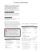
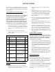
GENERAL INFORMATION IMPORTANT: To the user of this manual -- This manual is a guide for installing, operating, and maintaining this equipment. Refer to Table of Contents for page location of detailed information pertaining to questions that arise during installation, operation, service and maintenance, or troubleshooting this equipment.
THEORY OF OPERATION (see Figure 2) When unit power cord has been plugged into electrical outlet and power switch on back of unit has been flipped to ‘‘ON’’(up) position, compressor, condenser fan motor, and agitator motor will start and begin forming an ice bank. When full ice bank has been formed, compressor and condenser fan motor will stop but agitator motor will continue to operate circulating ice water bath in evaporator tank.
3 189159000 LINE LEGEND PRODUCT CO2 ICE WATER BATH DISPENSER DISPENSING VALVE (4) PRODUCT COIL (4) PRODUCT TANK (4) CHECK VALVE (4) CO2 REGULATOR (2) CO2 CYLINDER FIGURE 2.
THIS PAGE LEFT BLANK INTENTIONALLY 189159000 4
INSTALLATION This section covers unpacking and inspection, identification of LOOSE--SHIPPED PARTS, selecting location, installing unit, preparing unit for operation, and unit operation. 2. CUP REST (item 2) to be installed in DRIP TRAY (item 3). 3. DRIP TRAY (item 3) to be installed on unit by inserting rear edge of tray under lip of valve trim panel and lifting up until bottom tray supports are inserted in square holes provided in front panel. Lock drip tray in place by slight downward pressure.
ROUTING UNIT PRODUCT INLET LINES AND DRIP TRAY DRAIN HOSE OUT OF UNIT CABINET NOTE: An alternate arrangement for following installation method described would be to install available 6--inch leg kit (P/N 187416--000) or four caster kit (P/N 316290--000). IMPORTANT: When routing product inlet lines out through side of unit, use care to see that lines do not come in contact with compressor or hot discharge line. Accidental contact may result in foaming of dispensed product. 1.
B. Remove water fill hole plug from evaporator tank cover. 6. Plug unit power cord into a properly grounded electrical outlet. C. Fill evaporator tank until water starts flowing from overflow tube. USE LOW--MINERAL--CONTENT WATER WHERE A LOCAL WATER PROBLEM EXISTS. 7. Flip unit power switch to ‘‘ON’’(up) position. D. Install plug in water fill hole in evaporator tank cover. E. Install plug in end of evaporator tank overflow tube after full ice bank has been formed. 8.
THIS PAGE LEFT BLANK INTENTIONALLY 189159000 8
OPERATORS INSTRUCTIONS This section covers operating controls, daily pre-operation check, unit operation, adjustments, replenishing CO2 and product supplies, cleaning and sanitizing unit, checking condenser coil for restrictions, and checking ice water bath. OPERATING CONTROLS (see Figure 3) DISPENSING VALVE LEVER Dispensing valve lever need only to be pulled forward to dispense product and released when cup or glass is full.
THIS PAGE LEFT BLANK INTENTIONALLY 189159000 10
SERVICE AND MAINTENANCE This section describes service and maintenance procedures to be performed on the unit. 6. Check dispensing valves for dripping that indicates leaking and repair as necessary. IMPORTANT: Only qualified personnel should service internal components or electrical wiring.
WARNING: To avoid personal injury and/or property damage, always secure CO2 cylinder with safety chain to prevent it from falling. Should valve become accidentally damaged or broken off, CO2 cylinder can become an unguided missile. 4. Position CO2 cylinder and secure with safety chain. 5. Make sure gasket is in place inside CO2 regulator coupling nut, then install regulator on CO2 cylinder. 6.
*WATER FILL PLUG VALUE TRIM PANEL DISPENSING VALVE (4) 2 3 DRIP TRAY DRAIN HOSE ACCESS GRILLE (4) ACCESS GRILLE RETAINING SCREW (4) COMPENSATOR ADJUSTING SCREW COVER RETAINING SCREW (2) *EVAPORATOR TANK OVERFLOW TUBE PLUG EVAPORATOR TANK DRAIN HOSE UNIT POWER SWITCH *UNIT WITH SEALED EVAPORATOR TANK. FIGURE 3.
EVAPORATOR TANK ALUMINUM SCREW AGITATOR MOTOR ANODE FIGURE 4. EVAPORATOR TANK (STANDARD UNIT SHOWN) 7. Fill evaporator tank with water up to top of stainless steel product coils. USE LOW--MINERAL-CONTENT WATER WHERE A LOCAL WATER PROBLEM EXISTS. 8. Unit with sealed evaporator tank only. A. Install evaporator tank cover and coils line fittings, connect agitator motor ground wire and power cord, and connect product inlet lines swivel nut connections to fittings on evaporator tank cover. B.
CLEANING AND SANITIZING 6. If ice bank is dirty, allow it to melt. Hot water may be used to speed melting. DAILY CLEANING OF UNIT CAUTION: Never use an ice pick or other instrument to remove ice from evaporator. Such practice can result in punctured refrigerant circuit or damage to corrosion protective coating on evaporator tank. NOTE: Drip tray that is connected to drain hose routed to waste container or permanent drain need not be removed from unit to be cleaned.
WEEKLY CLEANING OF DISPENSING VALVES (see Figure 5) Dispensing valves should be cleaned at least weekly for proper operation. A convenient time to clean dispensing valves is at time unit is being sanitized. Perform following procedure to clean dispensing valves. 1. Remove quick disconnects (black) from product tanks outlets. 2. Open dispensing valves to relieve pressure on systems. 3. Remove dispensing valve knobs by pulling knobs up and off valves. 4.
11. Place waste container under applicable dispensing valve and blow residual water from system. WARNING: To avoid possible personal injury or property damage, do not attempt to remove product tank cover until CO2 pressure has been released from tank. 12. Repeat step 11 preceding to blow residual water from remaining systems. Install product tanks in systems. 10. Remove tank containing flush water from system and install clean empty product tank.
AGITATION MOTOR RECEPTACLE POWER SWITCH WIRE SPLICE CAP WHITE POWER CORD GREEN ICE BANK CONTROL COMPRESSOR CONDENSER FAN MOTOR CONTROL BOX 189159000 FIGURE 6.
FIGURE 7.
THIS PAGE LEFT BLANK INTENTIONALLY 189159000 20
TROUBLESHOOTING IMPORTANT: Only qualified personnel should service internal components or electrical wiring. WARNING: If repairs are to be made to carbonated water system, disconnect electrical power to Cooling Unit, shut off plain water and CO2 supplies, and relieve the carbonated water system pressure before proceeding. If repairs are to be made to syrup system, remove quick disconnects from applicable syrup tank, then relieve the system pressure before proceeding.
Trouble Probable Cause Remedy REFRIGERATION SYSTEM COMPRESSOR DOES NOT OPERATE. COMPRESSOR WILL NOT STOP AFTER SUFFICIENT ICE BANK IS FORMED. (NOTE--ICE BANK SHOULD JUST COVER CONTROL BULB). COMPRESSOR OPERATES CONTINUOUSLY BUT DOES NOT FORM SUFFICIENT ICE BANK. A. Ice bank sufficient. A. Refrigeration not called for. B. Unit power cord unplugged or unit power switch in ‘‘OFF’’ (down) position. B. Plug in power cord or flip power switch to ‘‘ON’’(up) position. C.
Trouble Probable Cause Remedy NOTE: If overload protector cuts out compressor, condenser fan motor will continue to run; otherwise; troubleshooting condenser fan motor problems is same as for “COMPRESSOR DOES NOT OPERATE” paragraph plus the following: CONDENSER FAN MOTOR NOT OPERATING. AGITATOR MOTOR NOT OPERATING. A. Jumper cord loose or disconnected from motor or terminal block. Broken wire is cord. A. Tighten connections or replace cord. B. Fan blade obstructed. B. Remove obstructions. C.
WARRANTY IMI Cornelius Inc. warrants that all equipment and parts are free from defects in material and workmanship under normal use and service. For a copy of the warranty applicable to your Cornelius, Remcor or Wilshire product, in your country, please write, fax or telephone the IMI Cornelius office nearest you. Please provide the equipment model number, serial number and the date of purchase. IMI Cornelius Offices AUSTRALIA D P.O.