
Programming instructions


2
1409
3. Place No. 4 ‘‘BEATER MOTOR CURRENT READ-
OUT’’ switch on DIP SWITCH assembly in ‘‘OFF’’
position to remove beaters motors current readings
from message display. After initial beater motors
currents adjustments, the electronics will automati-
cally self–calibrate the motors currents at comple-
tion of each defrost cycle.
ADJUSTMENTS AND PROGRAMMING MAIN
MENU SELECTIONS, COMPONENTS
‘‘DIAGNOSE’’ (DIAGNOSTIC MODE), AND
‘‘TOTALS’’ (DISPLAYED CYCLES AND
HOURS TOTALS) INTO UNIT
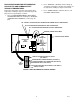
NOTE: The Unit control panel switches are as shown
in Figure 1.
The following instructions outline adjustments and pro-
gramming main menu selections, components ‘‘DIAG-
NOSE’’ (DIAGNOSTIC MODE), and ‘‘TOTALS’’ (DIS-
PLAYED CYCLES AND HOURS TOTALS) into Unit.
HIDDEN SECURITY
SWITCH
MESSAGE DISPLAY
FIGURE 1. CONTROL PANEL
Table 1. Main Menu Selections
MENU COMMANDS
MESSAGE DISPLAY
(EXAMPLE READOUTS)
“CLOCK” (TIME OF DAY) see note below C _ 1 2 - 0 0 A
“DEFROST” (AUTOMATIC) 3 D 1 0 - 0 0 A
“SLEEP” (SLEEP TIME) S 1 2 - 3 0 A _
“WAKE UP” (WAKE UP TIME) W _ 0 7 - 1 5 A
“VIS SET” (PRODUCT VISCOSITY SETTING) 1 2 _ _ _ _ 1 0
“VIS READ” (ACTUAL VISCOSITY READOUT) 1 6 _ _ _ _ 1 1
“SENSORS (TEMPERATURES READOUT) 7 5 * 7 5 * 7 5
“VOLTAGE” (DISPLAYED VOLTAGE READOUT) V R M S * 2 3 0
“DIAGNOSE” (DIAGNOSTIC MODE)
See Programming Components Diagnose into
Unit.
“TOTALS”
See Table 5 and programmings “TOTALS”
(DISPLAYED CYCLES AND HOURS TOTALS)
into unit.
NOTE: the “CLOCK” (TIME OF DAY) must be programmed into the Unit before “DEFROST” (AUTO-
MATIC) “SLEEP” (SLEEP TIME), and “WAKE UP” (WAKE UP TIME) will function.
NOTE: Plain water, CO
2
and syrup supplies to Unit
must be satisfied to turn off ‘‘H
2
O OUT’’, ‘‘CO
2
OUT’’, ‘‘SYRUP 1’’, and ‘‘SYRUP 2,’’ fault messages
on message display before adjustments and pro-
gramming procedures can be performed on the Unit.
PROGRAMMING MAIN MENU SELECTIONS
ONTO MESSAGE DISPLAY
The MAIN MENU SELECTIONS (see table 1) May be
brought up on the message display as follows: