
Programming instructions


IMI Cornelius Inc; 1991
Revised November 18, 1991
August 19, 1991
1409
IMI CORNELIUS INC.
One Cornelius Place
Anoka, MN. 55303–6234
Telephone (612) 421–6120
Facsimile (612) 422–3232
ADDENDUM TO SERVICE MANUALS
(IMI CORNELIUS INC; P/N 324229000, 326093000, AND 326142000)
FOR
FCB (FROZEN CARBONATED BEVERAGE) POST-MIX DISPENSERS
The purpose of this addendum is to provide programming instructions for the new V3 electronics now used in the FCB
Post–Mix Dispensers. The V3 electronics has new features and operations. The new features include a real-time clock
that allows programming of ‘‘DEFROST’’, ‘‘SLEEP’’ (SLEEP TIME) and ‘‘WAKE UP’’ (WAKE UP TIME) when you wish
these functions to operate. A new viscosity system program has simplified viscosity set–up by selecting the viscosity
from a range of 4 (wet) to 12 (stiff). The Unit will now automatically calibrate the beater motors (viscosity sensing) to
provide a long term viscosity consistency. The components ‘‘DIAGNOSTIC’’ (DIAGNOSTIC MODE) functions and other
set–up functions are now easily displayed on the message display. A ‘‘TOTALS’’ (DISPLAYED CYCLES AND HOURS
TOTALS) menu has been added to the new V3 electronics. Purpose of the ‘‘TOTALS’’ menu is to display total operation
hours and cycles readouts on the message display. Disregard all programming instructions documented in service
manual provided with your dispenser. All remaining information in your service manual and programming instructions in
this addendum are to be used. Retain this addendum as part of your service manual. Below is a list of the FCB Post–
Mix Dispensers model numbers contained in each manual.
SERVICE MANUALS DISPENSER MODEL NO.
324229000 416116068
326093000 416100073
416100068
496100068
326142–000 416120068
416120073
496120068
BEATER MOTOR SELECT
IMPORTANT: Before connecting electrical power to
Unit, refer to Unit nameplate and note if Unit is to be
operated with 50 or 60HZ electrical power and also
note beater motor manufacturer’s name.
1. Remove two screws securing Unit top cover, then
remove cover.
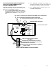
2. Remove four screws securing Unit upper control box
cover, then remove cover for access to the master
circuit board. (see Figure 2).
3. After noting if Unit is to be operated with 50 or 60HZ
electrical power and beater motors manufacturer’s
name, refer to Figure 2 and Table 3. to place DIP
switch assembly No. 6, No. 7 and No. 8 switches in
appropriate positions.
ADJUSTING BEATER MOTOR CURRENT
(EITHER SIDE)
IMPORTANT: Adjustment of Beater Motors Currents
should be performed with both freeze cylinders
thoroughly defrosted (partially defrosted freeze
cylinders may cause false current readings on
message display).
NOTE: Make sure No. 5 ‘‘MOTOR CURRENT SELF
CALIBRATION’’ switch on DIP SWITCH assembly on
master circuit board (see Figure 2) is in ‘‘OFF’’ posi-
tion. No. 5 switch in ‘‘OFF’’ position allows the ‘‘MO-
TOR CURRENT SELF CALIBRATION’’ electronics to
automatically self–calibrate the beaters motors cur-
rents at completion of each defrost cycle.
Adjust BEATER MOTOR CURRENT (EITHER SIDE) as
follows:
1. Place No. 4 ‘‘BEATER MOTOR CURRENT READ-
OUT’’ on DIP SWITCH assembly on master circuit
board (see Figure 2) in ‘‘ON’’ position. Both freeze
cylinders beater motors will start and operate and
beaters motors current ratings will be displayed on
message display.
2. Display should be adjusted to read
A150 B150 ± 2 by adjusting MOTOR CURRENT
ADJUSTMENTS located on No. 1 and No. 2 relay
circuit boards (see Figure 2). These figures will fluc-
tuate slightly with variations in line voltage and mo-
tor loads.