
Service manual

6
0713
WARNING: CO
2
Displaces Oxygen.
Strict Attention must be observed in
the prevention of CO
2
(carbon
dioxide) gas leaks in the entire CO
2
and soft
drink system. If a CO
2
gas leak is suspected,
particularly in a small area, immediately
ventilate the contaminated area before
attempting to repair the leak. Personnel
exposed to high concentration of CO
2
gas
will experience tremors which are followed
rapidly by loss of consciousness and
suffocation.
Connect bulk CO
2
tank supply line to barbed fitting
on CO
2
manifold. Connect with tubing clamp.
Installation with the optional high–pressure CO
2
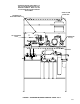
Regulator Assembly Kit (P/N 0708) (see Figure 7)
WARNING: To avoid personal injury
and/or property damage, always
secure CO
2
cylinders with safety
chain to prevent them from falling over.
Should the valve become accidentally
damaged of broken off, CO
2
cylinder can
cause serious personal injury.
A. Place two CO
2
cylinders next to the CO
2
mounting bracket. Fasten CO
2
cylinders
with safety chain.
B. Connect CO
2
lines from Control Panel, two
primary regulators on CO
2
cylinders.
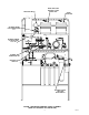
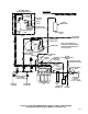
7. Installation with the Optional Water
PressureBooster System Kit (see applicable
Figure 3, 4, 5, or 6)
Note service valve on bottom of the Water Pressure
Booster System Water Tank. The water tank must be
pressurized with 40 5–PSI (2.76 .34 Bars) of
commercially dry air, CO
2
, or nitrogen gas through
the water tank service valve before putting system
into operation.
8. Water Surge Tank (see applicable Figure 3, 4,
5,, or 6)
Note service valve on bottom of the water surge
tank. The water surge tank must be pressurized with
12 2–PSI (.83 .14 Bars) of commercially dry air,
CO
2
, or nitrogen gas through the water tank service
valve before putting system into operation.
9. System Connected to Bulk CO
2
Supply (see
Figure 7)
A. Open shutoff valve on bulk CO
2
tank.
B. Adjust CO
2
regulator on bulk CO
2
tank to
105–PSI (7.24 Bars). Pull up on carbonator
tank relief valves for approximately two
seconds to bleed air from tanks.
C. Adjust CO
2
regulator for sugar–base syrup
tanks to 60–PSI (4.14 Bars).
D. Adjust CO
2
regulator for diet syrup tank to
12–PSI (.83 Bars).
10. System connected to two fifty pound CO
2
cylinders (see Figure 7).
A. Adjust two Primary CO
2
regulators to
105–PSI (7.24 Bars).
B. Adjust CO
2
regulator for sugar–base syrup
tanks to 60–PSI (4.14 Bars).
C. Adjust diet syrup tank CO
2
regulator to
12–PSI (.83 Bars).
11. Open all plain water shutoff valves on Beverage
Control Panel Assembly.
12. Check entire system for syrup, CO
2
gas, and
plain and carbonated water leaks. Repair if
leaks are evident.
13. Plug carbonator(s) and Water Pressure Booster
(if applicable) power cords into electrical outlets.
14. If Optional Air Compressor Kit is being used and
it is desired to operate with compressed air
rather than CO
2
gas pressure.
A. Plug air compressor power cord into
electrical outlet.
B. Place CO
2
/air switchover valve (see Figure
7) in air position.
15. Installation Using Optional Syrup Tank Kit
(P/N 0673) (see Figure 7.)
16. Operate all dispensing valves to bleed all air
from syrup systems.
Check entire system for leaks, (syrup, CO
2
gas, and
plain and carbonated water)repair if evident.
SEALING ENDS OF FLOOR CHASE (IF
APPLICABLE)
1. Pack ends of floor chase with paper to within
approximately six–inches from the top.
2. Seal ends of floor chase with plaster of paris
which may be purchased at a local building
materials store.