
Service manual

5
0713
1. Lay upper frame on its back. Slide telescoping
lower frame on to upper frame then secure with
tether strap.
2. Lift Assembled frame up and place in position
against wall.
3. Level control panel then secure Control Panel
Assembly to wall with six fasteners provided by
the installer.
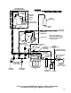
4. Using .156 I.D. tubing provided in installation kit,
connect one end of tubing to vented double
check valve (see applicable Figure 3, 4, 5, or 6),
then route other end of tubing to a permanent
floor drain.
5. Fasten tubing to frame assembly with wire ties
provided in installation kit.
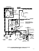
CONNECTING SUGAR–BASE SYRUP TANKS
CO
2
LINES TO CO
2
MANIFOLD
(see Figure 7)
1. Using .265 I.D. tubing, fittings, gas quick
disconnects, and tubing clamps, provided in the
installation kit, make up three gas lines to be
connected between the CO
2
manifold and the
sugar–base syrup tanks.
2. Connect three gas lines to CO
2
check valves on
CO
2
manifold. Seal connections with white
tapered gaskets.
CONNECTING DIET SYRUP TANK CO
2
LINE
TO DIET SYRUP CO
2
REGULATOR.
(see Figure 7)
3. Using .265 I.D. tubing, fittings, gas quick
disconnect, and tubing clamps, make up one
gas line to be connected between the Beverage
Control Panel Assembly diet–syrup tank.
4. Connect one gas line to check valve on outlet of
the diet–syrup CO
2
regulator. Seal connection
with white tapered gasket.
CONNECTING BEVERAGE CONTROL
PANEL ASSEMBLY TO POST–MIX
DISPENSER(S) AND OTHER EQUIPMENT TO
BE CONNECTED TO THE SYSTEM
(see Figure 7)
Refer to manual(s) provided with the Post–Mix
Dispenser(s) to connect plain water, carbonated
water, and syrup lines to the Dispenser(s).
Optional Syrup Tanks Kit (P/N 0673) is used to
connect four syrup tanks into the system.
Connect insulated plain water line between plain
water line connected to Post–Mix Dispenser cold
plate and the Orange Juice Dispenser.
PREPARATION FOR OPERATION
BEVERAGE CONTROL PANEL ASSEMBLY
NOTE: The Beverage Control Panel Assembly
must be connected to a water source with water
pressure between 45 and 75–PSI (3.10 and 5.17
Bars). If water pressure is over 75–PSI (5.17
Bars), an Optional Water Pressure Regulator Kit
(P/N 300919–00) must be installed. If plain water
source is below 45–PSI (3.10 Bars), an Optional
Water Pressure Booster Kit must be installed in
the system to boost water pressure to 75–PSI
(5.17 Bars).
IMPORTANT: DO NOT operate (if applicable) the
Optional Water Pressure Booster water pump
with no water connected to the Beverage Control
Panel Assembly. Operating water pump dry will
void its factory warranty.
1. Install loose–shipped water filter cartridges on
water filter assembly.
2. Make sure all shutoff valves on water manifold
and water filter assembly are in ‘‘OFF’’ position.
IMPORTANT: DO NOT operate carbonators or
water pressure booster system with no water in
the system. Operating pumps dry will cause
damage to the pumps which will void warranty.
3. Connect plain water line to Beverage Control
Panel Assembly.
4. Open plain water shutoff valve.
5. Beverage Control Panel Assembly equipped
with Everpure water filters (see applicable
Figure 3 or 5).
A. Connect length of garden hose to FILTER
‘‘ACTIVATION VALVE,’’ then route hose to
a permanent drain.
B. Open ‘‘ACTIVATION VALVE’’ and allow
approximately 28–gallons of water to flow
through the water filters, then close valve.
6. Standard Installation (see Figure 7).