
Service manual

4
0713
INSTALLATION
The Beverage Control Panel Assembly is designed
to filter,regulate pressure , and distribute plain and
carbonated water, CO
2
gas, and syrup to the soft
drink Beverage Dispenser and various other
equipment connected to the system.
NOTE: The Beverage Control Panel Assembly
was thoroughly inspected before leaving the
factory and the carrier has accepted and signed
for it. Any damage or irregularities should be
noted at the time of delivery (or not later than 15
days from date of deliver) and immediately
reported to the delivering carrier. Request a
written inspection report from Claims Inspector
to substantiate any necessary claim. File claim
with the delivering carrier, not with IMI Cornelius
Inc.
INSTALLING BEVERAGE CONTROL
PANEL ASSEMBLY
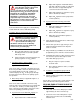
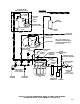
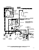
Your Beverage Control Panel Assembly may be
equipped with one or more of the optional kits as
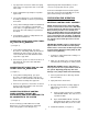
shown in Figure 2. Figure 1 shows the standard
Beverage Control Panel Assembly with no optional
kits and Figure 2 shows the panel assembly with
optional kits installed.
NOTE: Dedicated electrical outlets with proper
electrical requirements must be located close to
the Beverage Control Panel Assembly
installation location.
If your Beverage Control Panel Assembly is
equipped with either or both the optional air
compressor kit or the water pressure booster kit,
electrical outlets must also be located close to the
Panel.
No other electrical equipment should be connected to
these electrical circuits. ALL ELECTRICAL WIRING
MUST CONFORM TO NATIONAL AND LOCAL
ELECTRICAL CODES.
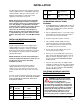
Table 2. Loose-Shipped Parts
Item
No. Part No. Name Qty.
1 300894–000 Water Surge Tank 1
2 300893–000 Strap, Surge Tank 1
3 300912 Tube Ass’y, .375 I.D.
By 56–in long
1
4 311304 Tapered Gasket,
Black
4
5 0590 Elbow Ass’y, Surge
Tank
1
INSTALLING WATER SURGE TANK (ITEM 1)
ON BEVERAGE CONTROL PANEL
ASSEMBLY
1. Install ELBOW ASS’Y SURGE TANK (item 5) in
top of WATER SURGE TANK (item 1) as shown
in Figure 16. Seal pipe thread connection with
pipe sealing compound.
2. Refer to applicable Figure 1 or 2 for water surge
tank location on Beverage Panel upper frame,
then remove two screws from frame.
3. Position surge tank in position on Panel.
4. Place STRAP, SURGE TANK (item 2) in
position around water surge tank and align
holes in strap with holes in frame where two
self–drilling screws were removed.
5. Secure strap to frame with the two screws
removed in step 2) preceding.
6. Connect one end of TUBE ASS’Y (item 33) to
water surge tank elbow 3/8–inch flare (5/8–18)
fitting as shown in applicable Figure 3, 4, 5, or
6. Seal connection with TAPERED GASKET,
BLACK (item 4).
7. Connect other end of tube assembly to water
manifold assembly 3/8–inch flare (5/8–18) fitting
on water filter assembly (see applicable Figure
3, 4, 5, or 6). Seal connection with TAPERED
GASKET, BLACK (item 4).
FASTENING BEVERAGE CONTROL
PANEL ASSEMBLY TO WALL
WARNING: The Beverage Control
Panel Assembly must be securely
fastened to the wall before
connecting the assembly into the system.
The Panel must be fastened to the wall with
six fasteners (provided by the Installer) and
each fastener must be capable of resisting a
200 pound (90.7 KG) pull. Care must taken
when handling the assembly as it is top
heavy and could fall and cause serious
personal injury and also equipment damage.
Secure Beverage Control Panel to wall as follows: