
Service manual


0713
24
8. Open Control Panel water inlet supply line
shutoff valve.
9. Plug carbonator(s) and the Water Pressure
Booster system power cords into electrical
outlets.
Checking Water Tank Air, CO
2
, or Nitrogen Gas
Pressure
NOTE: The Water Pressure Booster system water
tank must be completely drained before
proceeding to check and if necessary, pressurize
the tank with the proper amount of commercially
dry air, CO
2
, or nitrogen gas pressure. Proceed as
follows:
1. Unplug carbonator(s) and Water Pressure
Booster system power cords from electrical
outlets.
2. Close Control Panel water inlet supply line
shutoff valve.
3. Close plain water shutoff valve to Post–Mix
Dispenser.
4. Disconnect Post–Mix Dispenser plain water line
from shutoff valve.
5. Place bucket under shutoff valve. Open shutoff
valve and allow water to be purged from Water
Pressure Booster System water tank, then close
valve.
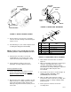
6. Note service valve (see applicable Figure 3, 4, 5,
or 6) on bottom of the Water Pressure Booster
system water tank. The water tank must be
pressurized to 40 5–PSI (2.76 .34 Bars) with
commercially dry air, CO, or nitrogen gas
pressure. Check and make sure water tank is
properly pressurized.
7. Open water inlet supply line shutoff valve.
8. Open Dispenser shutoff valve and allow water to
flow until a good stream of water flows from
valve, then close valve.
9. Reconnect Post–Mix Dispenser plain water line
to shutoff valve.
10. Plug both carbonators and Water Pressure
Booster System power cords into electrical
outlets.
Adjusting Pressure Switch ‘‘CUT OUT’’ (pump stops)
and‘‘CUT IN’’ (pump starts).
NOTE: The Water Pressure Booster system water
tank and the water system surge tank must be
completely drained and make sure they are
properly pressurized with commercially dry air,
CO
2
, or nitrogen gas pressure before checking
the water pump ‘‘CUT–IN’’ (pump starts) and
‘‘CUT–OUT’’ (pump stops). Proceed as follows:
1. Unplug carbonator(s) and Water Pressure
Booster system power cords from electrical
outlets.
2. Close Beverage Control Panel Assembly water
inlet supply line shutoff valve.
3. Close plain water shutoff valve for Post–Mix
Dispenser line. Disconnect water line from
shutoff valve.
4. Open shutoff valve and allow water to be purged
from water system surge tank and Water
Pressure Booster System water tank. DO NOT
CLOSE SHUTOFF VALVE AT THIS TIME.
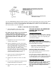
5. Note service valve on bottom of Water Pressure
Booster system water tank and water system
surge tank. The Water Pressure Booster system
water tank must be checked to make sure it is
pressurized to 40 ± 5–PSI (2.76 ± .034 Bars)
and the water system surge tank is pressurized
to 12 ± 2–PSI (.83 ± .14 Bars) with commercially
dry air, CO
2
, or nitrogen gas pressure.
6. Close Post–Mix Dispenser water outlet shutoff
valve, then open Control Panel plain water inlet
shutoff valve.
7. Open Dispenser shutoff valve and allow water to
flow until water surge tank and Water Pressure
Booster water tank are filled and a stream of
water flows from shutoff valve, then close valve.
CAUTION: To avoid damage, do not exceed the
maximum allowable system pressure of 85 ±
5–PSI (5.86 ± .35 Bars).
WARNING: Adjustment nuts are located
close to the high voltage terminals on
the pressure switch. To prevent possible electri-
cal shock, use an insulated 3/8 nut–driver to
make adjustments. Only qualified personnel
should perform adjustments on pressure
switch.