IMI CORNELIUS INC. ONE CORNELIUS PLACE ANOKA, MN. 55303–6234 TELEPHONE (800) 238–3600 FACSIMILE (612) 422–3232 WARRANTY IMI Cornelius Inc. warrants that all equipment and parts are free from defects in material and workmanship under normal use and service. For a copy of the warranty applicable to your Cornelius product, in your country, please write, fax or telephone the IMI Cornelius office nearest you. Please provide the equipment model number and the date of purchase.
IMI CORNELIUS INC. One Cornelius Place Anoka, MN 55303–6234 Telephone (800) 238–3600 Facsimile (612) 422–3246 BEVERAGE DISPENSING SUPPORT SYSTEM ASSEMBLY (MODEL NO. 2232MS) INSTALLATION AND SERVICE MANUAL MANFACTURED BY IMI CORNELIUS INC. ANOKA, MINNESOTA 55303–1592 BEVERAGE CONTROL PANEL ASS’Y Manual Part No.
TABLE 1. SPECIFICATIONS Model Numbers (Standard Assemblies W/O Optional Kits) Domestic Units: Beverage Control Panel (one carbonator) Requiring Connection to one Post-Mix Dispenser Beverage Control Panel (two carbonator) Requiring Connection to Two Post-Mix Dispenser 1416 0516 Export Units: Beverage Control Panel (one carbonator) Requiring Connection to One Post-Mix Dispenser Beverage Control Panel (two carbonator) Requiring Connection to Two Post-Mix Dispenser 1548 0187 Overall Dimension: Width 50.
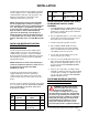
INSTALLATION The Beverage Control Panel Assembly is designed to filter,regulate pressure , and distribute plain and carbonated water, CO2 gas, and syrup to the soft drink Beverage Dispenser and various other equipment connected to the system. 4 5 0590 Elbow Ass’y, Surge Tank 1 2. Refer to applicable Figure 1 or 2 for water surge tank location on Beverage Panel upper frame, then remove two screws from frame. 3. Position surge tank in position on Panel. 4.
Optional Syrup Tanks Kit (P/N 0673) is used to connect four syrup tanks into the system. 1. Lay upper frame on its back. Slide telescoping lower frame on to upper frame then secure with tether strap. Connect insulated plain water line between plain water line connected to Post–Mix Dispenser cold plate and the Orange Juice Dispenser. 2. Lift Assembled frame up and place in position against wall. 3. Level control panel then secure Control Panel Assembly to wall with six fasteners provided by the installer.
WARNING: CO2 Displaces Oxygen. Strict Attention must be observed in the prevention of CO2 (carbon dioxide) gas leaks in the entire CO2 and soft drink system. If a CO2 gas leak is suspected, particularly in a small area, immediately ventilate the contaminated area before attempting to repair the leak. Personnel exposed to high concentration of CO2 gas will experience tremors which are followed rapidly by loss of consciousness and suffocation. B. Adjust CO2 regulator on bulk CO2 tank to 105–PSI (7.24 Bars).
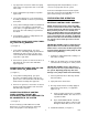
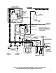
*BEVERAGE CONTROL PANEL MODEL 0817 AND 0516 ARE EQUIPPED WITH TWO CARBONATOR ASSEMBLIES. MODEL 1416 AND 1548 ARE EQUIPPED WITH ONE CARBONATOR ASSEMBLY. WATER SYSTEM SURGE TANK SECONDARY CO2 REGULATOR PANEL ASS’Y CO2 SWITCHOVER VALVE CARBONATOR ASS’Y(2) PLUG FIGURE 1.
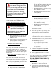
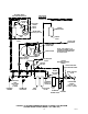
PRESSURE SWITCH WATER PRESSURE BOOSTER SYSTEM WATER TANK WATER SURGE TANK OPTIONAL WATER PRESSURE BOOSTER KIT OPTIONAL PRIMARY CO2 REGULATOR ASS’Y KIT OPTIONAL AIR COMPRESSOR KIT OPTIONAL SYRUP TANKS KIT OPTIONAL WATER PRESSURE REGULATOR KIT FIGURE 2.
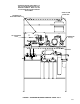
OPTIONAL WATER PRESSURE BOOSTER KIT LINE LEGEND PLAIN WATER CARBONATED WATER SHUTOFF VALVE PRESSURE SWITCH CHECK VALVE WATER SURGE TANK WATER PUMP (90–GPH) (341–LPH) WATER TANK SERVICE VALVE SERVICE VALVE TO POST–MIX DISPENSER CARBONATED WATER TANK WATER PUMP CARBONATOR DOUBLE VENTED CHECK VALVE(2) CAPPED WATER PRESSURE GAUGE SHUTOFF STANDARD VALVE(7) TUBE ASS’Y (SEE NOTE) NOTE: THIS TUBE ASS’Y IS CONNECTED WHEN OPTIONAL WATER PRESSURE BOOSTER KIT IS NOT USED.
OPTIONAL WATER PRESSURE BOOSTER KIT SHUTOFF VALVE LINE LEGEND PLAIN WATER CARBONATED WATER PRESSURE SWITCH CHECK VALVE WATER SURGE TANK WATER PUMP (90–GPH) (341–LPH) WATER TANK SERVICE VALVE SERVICE VALVE TO POST–MIX DISPENSER CARBONATED WATER TANK WATER PUMP CARBONATOR DOUBLE VENTED CHECK VALVE(2) CAPPED WATER PRESSURE GAUGE NOTE: THIS TUBE ASS’Y IS CONNECTED WHEN OPTIONAL WATER PRESSURE BOOSTER KIT IS NOT USED.
OPTIONAL WATER PRESSURE BOOSTER KIT SHUTOFF VALVE LINE LEGEND PLAIN WATER CARBONATED WATER NOTE: THIS TUBE ASS’Y IS CONNECTED WHEN OPTIONAL WATER PRESSURE BOOSTER KIT IS NOT USED.
OPTIONAL WATER PRESSURE BOOSTER KIT SHUTOFF VALVE LINE LEGEND PLAIN WATER CARBONATED WATER PRESSURE SWITCH CHECK VALVE WATER SURGE TANK WATER PUMP (90–GPH) (341–LPH) NOTE: THIS TUBE ASS’Y IS CONNECTED WHEN OPTIONAL WATER PRESSURE BOOSTER KIT IS NOT USED.
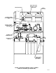
AIR COMPRESSOR KIT (OPTIONAL) CONDENSATION DRAIN TUBE CONDENSATION TANK CONNECT TO CARBONATORS CO2 REGULATOR ASS’Y KIT (OPTIONAL) TO CO2 CYLINDER CO2/AIR CHANGEOVER VALVE SUGAR BASED SYRUP (60–PSI) (4.14 BARS) DIET SYRUP (12–PSI) (.
1 2 3 4 5 6 7 8 9 10 14 11 12 13 14 15 16 0713 COKE BULK TANK FIGURE 8.
CONN NBR 1 2 3 4 5 15 6 7 8 Part No. DESCRIPTION QTY. CONN NBR 9 770409000 3/8 Swivel - 3/8 Barb Elbow 1 311304000 Gasket 1 309852000 170 Oeitker Clamp 2 770695000 1/2 x 3/8 x 3/8 Barb Tee 1 309852000 170 Oeitker Clamp 4 319681000 210 Oeitker Clamp 2 11 176206000 1/2 Nut 1 12 176205000 1/2 x 3/8 Stem 311304000 Gasket 309852000 Part No. DESCRIPTION QTY.
1 coke orange coke 3 4 1 5 6 7 8 9 10 11 12 13 14 15 16 16 17 18 partnum FIGURE 9.
CONN NBR 1 2 3 4 5 17 6 7 8 Part No. DESCRIPTION QTY. CONN NBR 9 770409000 3/8 Swivel -///8 Barb Elbow 1 311304000 Gasket 1 309852000 170 Oeitker Clamp 2 770695000 1/2 x 3/8 x 3/8 Barb Tee 1 309852000 170 Oeitker Clamp 4 319681000 210 Oeitker Clamp 2 11 176206000 1/2 Swivel Nut 1 12 176205000 Swivel Barb 311304000 Gasket 309852000 Part No. DESCRIPTION QTY.
1 2 3 4 5 6 7 8 9 10 11 12 13 14 15 18 16 17 ORANGE DIET partnum SPRITE 18 FIGURE 10.
CONN NBR 1 2 3 4 5 19 6 7 8 9 Part No. DESCRIPTION QTY.
2 3 4 5 6 7 8 9 10 11 12 13 14 15 16 20 17 18 19 partnum FIGURE 11.
CONN NBR 1 2 3 4 5 21 6 7 8 9 Part No. DESCRIPTION QTY.
SERVICE AND MAINTENANCE BEVERAGE CONTROL PANEL ASSEMBLY SERVICE AND MAINTENANCE CARBONATOR ASSEMBLY SERVICE AND MAINTENANCE Refer to manual provided with carbonator assembly for service and maintenance instructions. ADJUSTING PRIMARY CO2 REGULATORS 4. Disconnect Post–Mix Dispenser plain water line from shutoff valve. 5. Place bucket under shutoff valve. Open shutoff valve and allow water to be purged from surge tank. DO NOT CLOSE VALVE AT THIS TIME. 6.
PRESSURE SWITCH WATER PUMP LIQUID CHECK VALVE WATER STRAINER SCREEN (P/N 315348–000) WATER PUMP MOTOR O–RING (P/N 315349–000) FIGURE 13. WATER PUMP AND MOTOR SCREEN RETAINER 1 3 FIGURE 12. WATER STRAINER SCREEN 2 6 5. Inspect strainer screen for holes, restrictions, corrosion, and other damage. Discard damaged strainer screen. 6. Check O–Ring on screen retainer. Replace worn or damaged O–Ring (P/N 315349–000).
8. Open Control Panel water inlet supply line shutoff valve. 9. Plug carbonator(s) and the Water Pressure Booster system power cords into electrical outlets. Checking Water Tank Air, CO2, or Nitrogen Gas Pressure NOTE: The Water Pressure Booster system water tank must be completely drained before proceeding to check and if necessary, pressurize the tank with the proper amount of commercially dry air, CO2, or nitrogen gas pressure. Proceed as follows: 1.
Note: The DIFFERENTIAL adjustment (20–psi) between ‘‘CUT–IN’’ (water pump starts) and ‘‘CUT–OUT’’ (water pump stops) has been adjusted at the factory and should require no further adjustment. Should differential adjustment become necessary, turn DIFFERENTIAL ADJUSTMENT nut clockwise to increase differential or turn nut counterclockwise to decrease differential. FIGURE 15. PRESSURE SWITCH ADJUSTMENT 8. Using 5/16 nutdriver, remove nut securing pressure switch cover, then remove cover.
1. Fully close (clockwise) CO2 cylinder valve. 2. Slowly loosen CO2 regulator assembly coupling nut allowing CO2 pressure to escape, then remove regulator assembly from empty CO2 cylinder. 3. Unfasten safety chain and remove empty CO2 cylinder. WARNING: To avoid personal injury and/or property damage, always secure CO2 cylinder with safety chain to prevent if from falling over. Should the valve become accidentally damaged or broken off, CO2 cylinder can cause serious personal injury. 4.
TROUBLESHOOTING IMPORTANT: Only qualified personnel should service internal components or electrical wiring. WARNING: If repairs are to be made to carbonated water system, disconnect electrical power to Cooling Unit, shut off plain water and CO2 supplies, and relieve the carbonated water system pressure before proceeding. If repairs are to be made to syrup system, remove quick disconnects from applicable syrup tank, then relieve the system pressure before proceeding.
Trouble WATER PUMP ‘‘LONG CYCLES’’ (CON’T) WATER INLET PRESSURE GAUGE READS TOO LOW WATER INLET PRESSURE GAUGE READS TOO HIGH AIR COMPRESSOR DOES NOT OPERATE AIR COMPRESSOR DOES NOT OPERATE (CON’T) AIR COMPRESSOR ‘SHORT CYCLES’’ Probable Cause Remedy D. Water pre–filter is plugged (this condition will be accompanied by a change in pitch of the water pump when operating.) D. If water inlet pressure gauge reads below 5–PSI (.34 Bars) while water pump is operating,replace water pre–filter. E.
Trouble Probable Cause Remedy DISPENSED DRINKS HAVE ‘OFF’’ TASTE A. Air tank contains excessive water (condensation). A. Drain condensation from air tank, then sanitize syrup systems and replace contaminated syrup. AIR COMPRESSOR‘‘LONG CYCLES’’ A. Condensation drain valve on air tank is in ‘‘OPEN‘’ position. A. Place condensation drain valve in ‘‘CLOSED’’ position. B. Pressure relief valve on air tank lid is open B. Close air tank lid relief valve. C. Air compressor air filter is clogged.
FIGURE 1. WIRING DIAGRAM (CARBONATOR) FIGURE 2.
27 11 27 10 13 1 2 24 20 15 22 15 13 13 5 8 7 23 15 25 15 26 12 15 21 3 9 6 13 4 13 16 17 19 FIGURE 16.
BEVERAGE CONTROL PANEL ASS’Y Item No. Part No. Name Beverage Control Panel Ass’y One Carbonator, Domestic 0516 Beverage Control Panel Ass’y Two Carbonator, Domestic 1548 Part No. Name 14 *1300 Washer, .229 I.D. By .049CS 15 311304 Tapered Gasket Black 16 318556 Hanger Beverage Control Panel Ass’y One Caronbator, Export 17 189429 Hex Nut Keps, 1/4-20 Domestic *321811 Hex Nut, Keps, No.
2 6 7 8 10 9 1 7 8 10 11 6 12 4 13 7 8 10 4 5 4 5 3 6 7 8 10 FIGURE 17. CO2 REGULATOR ASS’Y (P/N 0483) Item No. Part No. Name 0483 CO2 Regulator Ass’y 1 0137 Manifold Ass’y Carbonataor (see Figure 5-3) 2 0138 Regulator Ass’y syrup (see Figure 5-5) 3 0145 Manifold and Bracket Ass’y CO2 (see Figure 5-8) 4 178025-100 Tapered Gasket, White 5 311732 Connector, Swivel, 7/16-20 6 315499 Cap, 7/16 7 398022-400 Machine Screw, SL RD HD Stainless Steel, No.
11 10 9 3 8 4 3 2 6 5 1 Item No. 7 Part No.
1 4 10 5 15 6 11 8 13 7 14 12 16 9 2 3 FIGURE 21. CO2 REGULATOR ASS’Y Item No. 1 2 3 Part No. Item No. Name Part No.
6 4 1 Item No. 5 7 3 2 Part No. Name 183302-100 Check Valve Ass’y 1 183300-003 Manifold, 3 Port 2 183295-100 Body 3 183298 Retainer, Spring 4 183296 Ball 5 183297 Spring 6 183294 Quad Ring, .145 I.D. By .070 CS 7 315499 Cap FIGURE 22. CHECK VALVE AND MANIFOLD ASS’Y (P/N 183302-100) 7 4 1 2 3 5 Item No. Part No.
34 32 20 19 33 35 36 37 52 21 1 23 2 22 26 1 38 3 39 26 5 6 7 8 9 10 4 23 24 27 14 28 16 1 47 25 31 13 11 12 29 15 17 18 1 13 11 46 45 44 43 42 41 40 29 51 50 49 48 30 FIGURE 24.
LARGE RESERVE CARBONATOR Item No. Part No. Name Item No. Part No. Name 26 *200498-003 Hex Nut Keps, No. 8-32 27 *312578 Machine Screw, SI Rd Hd, No.
3 Item No. 5 4 1 2 Part No. Name 300914 Water Manifold Ass’y 1 0191 Manifold Ass’y with Shut-Off Valve 2 300922 Water Pressure Regulator 3 301102 Gauge, 100 PSI 4 0190 Manifold Ass’y with Shut-Off Valve 5 0881 Check Valve, Double Vented FIGURE 25. WATER MANIFOLD ASS’Y (P/N 300914-000) Item No. 1 1 Part No. Name 0193 Water Manifold Ass’y 300882 Shut-Off ValveShut-Off Valve FIGURE 26. WATER OUTLET VALVE ASS’Y (P/N 0193) 2 6 4 Item No. 6 7 Part No.
Item No. 12 1 6 3 2 10 8 4 5 Name Motor, 115V. 60 HZ, Domestic 320626 Motor, 230V.
2 Item No. 6 4 3 4 5 4 1 4 5 Part No. Name 1 311904 Changeover Valve 2 0606 Regulator Ass’y (see Figure 5-17) 3 176065 Fitting, Swivel, 7/16-20 4 178025-100 Tapered Gasket, White 5 310822 Fitting, 7/16-20 6 176168-100 Fitting, 1/4 NPT By 7/16-20 *zinc Plated Steel Unless Otherwise Indicated. FIGURE 31. REGULATOR ASS’Y, HI-PRESSURE (P/N 0650) 2 Item No. 6 7 8 5 9 11 10 3 1 4 Part No.