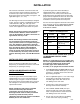
IMI CORNELIUS INC. One Cornelius Place Anoka, MN 55303–6234 Telephone (800) 238–3600 Facsimile (612) 422–3246 BEVERAGE DISPENSING SUPPORT SYSTEM ASSEMBLY (MODEL NO. 2232MS) INSTALLATION AND SERVICE MANUAL MANFACTURED BY IMI CORNELIUS INC. ANOKA, MINNESOTA 55303–1592 BEVERAGE CONTROL PANEL ASS’Y Manual Part No.
GENERAL DESCRIPTION Shipments of returned merchandise sent collect will not be accepted. Used or discontinued equipment will not be accepted for credit under any circumstances. Item returned to IMI Cornelius Inc; for credit or reimbursement, having a value of less the 25.00 dollars will not receive credit. Warranty Registration Data (to be filled out by customer) Model Number; Serial Number; Install Date; Local Authorized Service Center; CLAIMS...
COMPLETE SERVICE Your trained Cornelius Sales Person stands ready to serve you with ordering and technical assistance. He can also offer you success proven merchandising ideas and placement programs that will help you to locate Cornelius beverage equipment in retail accounts. Complete repair and installation service by factory trained personnel is available at Authorized Service Centers. Addresses are available at your request. Spare parts may also be ordered from our Authorized Service Centers.
TABLE 1. SPECIFICATIONS Model Numbers (Standard Assemblies W/O Optional Kits) Domestic Units: Beverage Control Panel (one carbonator) Requiring Connection to one Post-Mix Dispenser Beverage Control Panel (two carbonator) Requiring Connection to Two Post-Mix Dispenser 1416 0516 Export Units: Beverage Control Panel (one carbonator) Requiring Connection to One Post-Mix Dispenser Beverage Control Panel (two carbonator) Requiring Connection to Two Post-Mix Dispenser 1548 0187 Overall Dimension: Width 50.
INSTALLATION This manual is intended to assist the installer and service personnel in the installation, operation, and maintenance procedures to be performed on the Beverage Control Panel Assembly (see Figure 1 and applicable Figure 3, 4, 5, or 6).
. Connect one end of TUBE ASS’Y (item 33) to water surge tank elbow assembly 3/8–inch flare (5/8–18) fitting as shown in applicable Figure 3, 4, 5, or 6. Seal connection with TAPERED GASKET, BLACK (item 4). CONNECTING SUGAR–BASE SYRUP TANKS CO2 LINES TO BEVERAGE CONTROL PANEL ASSEMBLY CO2 MANIFOLD (see Figure 7) 1. Using .265 I.D.
2. Make sure all shutoff valves on water manifold assembly and water filter assembly are in ‘‘OFF’’ position. Center–Island and Second Dispenser Installation with Optional Syrup Tanks Hookup (see Figure NO TAG) Connect CO2, plain water, carbonated water, and syrup lines between Beverage Control Panel Assembly, the Post–Mix Dispensers, and other equipment to be connected to the system. Optional Syrup Tanks Kit (P/N 0673) is used to connect four syrup tanks into the system.
A. Locate two full CO2 cylinders in upright positions next to the CO2 mounting bracket. Fasten CO2 cylinders with safety chain. B. Connect two CO2 lines from Beverage Control Panel Assembly two primary CO2 regulators to the CO2 cylinders. 7. Installation employing the Optional Water PressureBooster System Kit (see applicable Figure 3, 4, 5, or 6) Note service valve on bottom of the Water Pressure Booster System Water Tank. The water tank must be pressurized with 40 5–PSI (2.76 .
A. Connect bulk syrup tank into system. B. Connect three other flavors syrup tanks into syrup systems. CHECKING ENTIRE SYSTEM FOR SYRUP, CO2 GAS, AND PLAIN AND CARBONATED WATER LEAKS Check entire system for syrup, CO2 gas, and plain and carbonated water leaks and repair if evident. 18. Installation Using Optional Syrup Tank Kit (P/N 0673) (see Figure 7.) A. Connect four syrup tanks into syrup systems. B. Connect three other flavors syrup tanks into syrup systems.
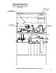
*BEVERAGE CONTROL PANEL MODEL 0817 AND 0516 ARE EQUIPPED WITH TWO CARBONATOR ASSEMBLIES. MODEL 1416 AND 1548 ARE EQUIPPED WITH ONE CARBONATOR ASSEMBLY. WATER SYSTEM SURGE TANK SECONDARY CO2 REGULATOR PANEL ASS’Y CO2 SWITCHOVER VALVE CARBONATOR ASS’Y(2) PLUG FIGURE 1.
PRESSURE SWITCH WATER PRESSURE BOOSTER SYSTEM WATER TANK WATER SURGE TANK OPTIONAL WATER PRESSURE BOOSTER KIT OPTIONAL PRIMARY CO2 REGULATOR ASS’Y KIT OPTIONAL AIR COMPRESSOR KIT OPTIONAL SYRUP TANKS KIT OPTIONAL WATER PRESSURE REGULATOR KIT FIGURE 2.
OPTIONAL WATER PRESSURE BOOSTER KIT LINE LEGEND PLAIN WATER CARBONATED WATER SHUTOFF VALVE PRESSURE SWITCH CHECK VALVE WATER SURGE TANK WATER PUMP (90–GPH) (341–LPH) WATER TANK SERVICE VALVE SERVICE VALVE TO POST–MIX DISPENSER CARBONATED WATER TANK WATER PUMP CARBONATOR DOUBLE VENTED CHECK VALVE(2) CAPPED WATER PRESSURE GAUGE SHUTOFF STANDARD VALVE(7) TUBE ASS’Y (SEE NOTE) NOTE: THIS TUBE ASS’Y IS CONNECTED WHEN OPTIONAL WATER PRESSURE BOOSTER KIT IS NOT USED.
OPTIONAL WATER PRESSURE BOOSTER KIT SHUTOFF VALVE LINE LEGEND PLAIN WATER CARBONATED WATER PRESSURE SWITCH CHECK VALVE WATER SURGE TANK WATER PUMP (90–GPH) (341–LPH) WATER TANK SERVICE VALVE SERVICE VALVE TO POST–MIX DISPENSER CARBONATED WATER TANK WATER PUMP CARBONATOR DOUBLE VENTED CHECK VALVE(2) CAPPED WATER PRESSURE GAUGE NOTE: THIS TUBE ASS’Y IS CONNECTED WHEN OPTIONAL WATER PRESSURE BOOSTER KIT IS NOT USED.
OPTIONAL WATER PRESSURE BOOSTER KIT SHUTOFF VALVE LINE LEGEND PLAIN WATER CARBONATED WATER NOTE: THIS TUBE ASS’Y IS CONNECTED WHEN OPTIONAL WATER PRESSURE BOOSTER KIT IS NOT USED.
OPTIONAL WATER PRESSURE BOOSTER KIT SHUTOFF VALVE LINE LEGEND PLAIN WATER CARBONATED WATER PRESSURE SWITCH CHECK VALVE WATER SURGE TANK WATER PUMP (90–GPH) (341–LPH) NOTE: THIS TUBE ASS’Y IS CONNECTED WHEN OPTIONAL WATER PRESSURE BOOSTER KIT IS NOT USED.
AIR COMPRESSOR KIT (OPTIONAL) CONDENSATION DRAIN TUBE CONDENSATION TANK CONNECT TO CARBONATORS CO2 REGULATOR ASS’Y KIT (OPTIONAL) TO CO2 CYLINDER CO2/AIR CHANGEOVER VALVE SUGAR BASED SYRUP (60–PSI) (4.14 BARS) DIET SYRUP (12–PSI) (.
1 2 3 4 5 6 7 8 9 10 16 11 12 13 14 15 16 0713 COKE BULK TANK FIGURE 8.
CONN NBR 1 2 3 4 5 17 6 7 8 Part No. DESCRIPTION QTY. CONN NBR 9 770409000 3/8 Swivel - 3/8 Barb Elbow 1 311304000 Gasket 1 309852000 170 Oeitker Clamp 2 770695000 1/2 x 3/8 x 3/8 Barb Tee 1 309852000 170 Oeitker Clamp 4 319681000 210 Oeitker Clamp 2 11 176206000 1/2 Nut 1 12 176205000 1/2 x 3/8 Stem 311304000 Gasket 309852000 Part No. DESCRIPTION QTY.
1 coke orange coke 3 4 1 5 6 7 8 9 10 11 12 13 14 15 16 18 17 18 partnum FIGURE 9.
CONN NBR 1 2 3 4 5 19 6 7 8 Part No. DESCRIPTION QTY. CONN NBR 9 770409000 3/8 Swivel -///8 Barb Elbow 1 311304000 Gasket 1 309852000 170 Oeitker Clamp 2 770695000 1/2 x 3/8 x 3/8 Barb Tee 1 309852000 170 Oeitker Clamp 4 319681000 210 Oeitker Clamp 2 11 176206000 1/2 Swivel Nut 1 12 176205000 Swivel Barb 311304000 Gasket 309852000 Part No. DESCRIPTION QTY.
1 2 3 4 5 6 7 8 9 10 11 12 13 14 15 20 16 17 ORANGE DIET partnum SPRITE 18 FIGURE 10.
CONN NBR 1 2 3 4 5 21 6 7 8 9 Part No. DESCRIPTION QTY.
2 3 4 5 6 7 8 9 10 11 12 13 14 15 16 22 17 18 19 partnum FIGURE 11.
CONN NBR 1 2 3 4 5 23 6 7 8 9 Part No. DESCRIPTION QTY.
SERVICE AND MAINTENANCE POST–MIX DISPENSER SERVICE AND MAINTENANCE CHECKING PLAIN WATER SYSTEM SURGE TANK AIR, CO2 OR NITROGEN GAS PRESSURE (see applicable Figure 3, 4, 5, or 6). Refer to manual provided with the Post–Mix Dispenser for service and maintenance instructions. NOTE: The plain water surge tank must be completely drained before proceeding to check and if necessary, pressurize the tank with the proper amount of ‘‘commercially dry air, CO2, or nitrogen gas pressure.
2. Close Beverage Control Panel Assembly water inlet supply line shutoff valve. PRESSURE SWITCH LIQUID CHECK VALVE 3. Loosen screen retainer, then pull screen retainer and strainer screen from water pump. (see Figure 12). 4. Pull strainer screen from screen retainer. Clean any sediment from screen retainer and pump screen retainer port. WATER PUMP WATER PUMP MOTOR WATER STRAINER SCREEN (P/N 315348–000) FIGURE 13. WATER PUMP AND MOTOR 1 3 2 6 4 O–RING (P/N 315349–000) SCREEN RETAINER FIGURE 12.
8. Open Beverage Control Panel Assembly water inlet supply line shutoff valve. 9. Plug carbonator(s) and the Water Pressure Booster system power cords into electrical outlets. Checking Water Tank Air, CO2, or Nitrogen Gas Pressure NOTE: The Water Pressure Booster system water tank must be completely drained before proceeding to check and if necessary, pressurize the tank with the proper amount of commercially dry air, CO2, or nitrogen gas pressure.
Note: The DIFFERENTIAL adjustment (20–psi) between ‘‘CUT–IN’’ (water pump starts) and ‘‘CUT–OUT’’ (water pump stops) has been adjusted at the factory and should require no further adjustment. Should differential adjustment become necessary, turn DIFFERENTIAL ADJUSTMENT nut clockwise to increase differential or turn nut counterclockwise to decrease differential. FIGURE 15. PRESSURE SWITCH ADJUSTMENT 8. Using 5/16 nutdriver, remove nut securing pressure switch cover, then remove cover.
11. Connect syrup out quick disconnects to all syrup tanks. WATER FILTERS REPLACEMENT Refer to Water Filtration System manual for water filters replacement instructions. SANITIZING SYRUP SYSTEMS The syrup systems should be sanitized every 90–days using Chlor–Tergent (Oakite Products, Inc.) or equivalent sanitizer. Refer to manual provided with the Post–Mix Dispenser for sanitizing instructions. REPLENISHING CO2 SUPPLY FIGURE 16. SYRUP LINE STRAIANER 1. Using chlor–tergent (Oakite Products, Inc.
1. Remove CO2 disconnect and syrup disconnect from empty syrup tank, then remove tank. 2. Place full syrup tank in position, then connect CO2 disconnect and syrup disconnect to full syrup tank. SYRUP FLAVOR CHANGE Sanitize applicable syrup system as instructed, then install full tank of new flavor syrup.
TROUBLESHOOTING IMPORTANT: Only qualified personnel should service internal components or electrical wiring. WARNING: If repairs are to be made to carbonated water system, disconnect electrical power to Cooling Unit, shut off plain water and CO2 supplies, and relieve the carbonated water system pressure before proceeding. If repairs are to be made to syrup system, remove quick disconnects from applicable syrup tank, then relieve the system pressure before proceeding.
Trouble WATER PUMP ‘‘LONG CYCLES’’ (CON’T) WATER INLET PRESSURE GAUGE READS TOO LOW WATER INLET PRESSURE GAUGE READS TOO HIGH AIR COMPRESSOR DOES NOT OPERATE Probable Cause Remedy C. Water pump pressure switch is not correctly adjusted. C. Verify pressure switch ‘‘CUT–OUT’’ pressure is adjusted at 85 ± 5 PSI (5.86 ±.35 Bars) or ‘‘CUT–IN’’ pressure is adjusted at 60 ± 5 PSI (4.14 ± .35 Bars). Have Service Technician readjust pressure switch. D.
Trouble AIR COMPRESSOR DOES NOT OPERATE (CON’T) Probable Cause Remedy E. Air/CO2 changeover valve on CO2 panel set to CO2 position. E. Select desired valve position. F. Air compressor is inoperative. F. Replace air compressor. A. Air compressor pressure switch is not correctly adjusted. A. Have Service Technician adjust pressure switch. B. Air tank contains water (condensation). B. Drain water (condensation) from air tank by opening condensation drain tube valve.
FIGURE 1. WIRING DIAGRAM (CARBONATOR) FIGURE 2.
FIGURE 3.
27 11 27 10 13 1 2 24 20 15 22 15 13 13 5 8 7 23 15 25 15 26 12 15 21 3 9 6 13 4 13 16 17 19 FIGURE 17.
BEVERAGE CONTROL PANEL ASS’Y Item No. Part No. Name Beverage Control Panel Ass’y One Carbonator, Domestic 0516 Beverage Control Panel Ass’y Two Carbonator, Domestic 1548 Part No. Name 14 *1300 Washer, .229 I.D. By .049CS 15 311304 Tapered Gasket Black 16 318556 Hanger Beverage Control Panel Ass’y One Caronbator, Export 17 189429 Hex Nut Keps, 1/4-20 Domestic *321811 Hex Nut, Keps, No.
2 6 7 8 10 9 1 7 8 10 11 6 12 4 13 7 8 10 4 5 4 5 3 6 7 8 10 FIGURE 18. CO2 REGULATOR ASS’Y (P/N 0483) Item No. Part No. Name 0483 CO2 Regulator Ass’y 1 0137 Manifold Ass’y Carbonataor (see Figure 5-3) 2 0138 Regulator Ass’y syrup (see Figure 5-5) 3 0145 Manifold and Bracket Ass’y CO2 (see Figure 5-8) 4 178025-100 Tapered Gasket, White 5 311732 Connector, Swivel, 7/16-20 6 315499 Cap, 7/16 7 398022-400 Machine Screw, SL RD HD Stainless Steel, No.
11 10 9 3 8 4 3 2 6 5 1 Item No. 7 Part No.
1 4 10 5 15 6 11 8 13 7 14 12 16 9 2 3 FIGURE 22. CO2 REGULATOR ASS’Y Item No. 1 2 3 Part No. Item No. Name Part No.
6 4 1 Item No. 5 7 3 2 Part No. Name 183302-100 Check Valve Ass’y 1 183300-003 Manifold, 3 Port 2 183295-100 Body 3 183298 Retainer, Spring 4 183296 Ball 5 183297 Spring 6 183294 Quad Ring, .145 I.D. By .070 CS 7 315499 Cap FIGURE 23. CHECK VALVE AND MANIFOLD ASS’Y (P/N 183302-100) 7 4 1 2 3 5 Item No. Part No.
34 32 20 19 33 35 36 37 52 21 1 23 2 22 26 1 38 3 39 26 5 6 7 8 9 10 4 23 24 27 14 28 16 1 47 25 31 13 11 12 29 15 17 18 1 13 11 46 45 44 43 42 41 40 29 51 50 49 48 30 FIGURE 25.
LARGE RESERVE CARBONATOR Item No. Part No. Name Item No. Part No. Name 26 *200498-003 Hex Nut Keps, No. 8-32 27 *312578 Machine Screw, SI Rd Hd, No.
3 Item No. 5 4 1 2 Part No. Name 300914 Water Manifold Ass’y 1 0191 Manifold Ass’y with Shut-Off Valve 2 300922 Water Pressure Regulator 3 301102 Gauge, 100 PSI 4 0190 Manifold Ass’y with Shut-Off Valve 5 0881 Check Valve, Double Vented FIGURE 26. WATER MANIFOLD ASS’Y (P/N 300914-000) Item No. 1 1 Part No. Name 0193 Water Manifold Ass’y 300882 Shut-Off ValveShut-Off Valve FIGURE 27. WATER OUTLET VALVE ASS’Y (P/N 0193) 2 6 4 Item No. 6 7 Part No.
Item No. 12 1 6 3 2 10 8 4 5 Name Motor, 115V. 60 HZ, Domestic 320626 Motor, 230V.
2 Item No. 6 4 3 4 5 4 1 4 5 Part No. Name 1 311904 Changeover Valve 2 0606 Regulator Ass’y (see Figure 5-17) 3 176065 Fitting, Swivel, 7/16-20 4 178025-100 Tapered Gasket, White 5 310822 Fitting, 7/16-20 6 176168-100 Fitting, 1/4 NPT By 7/16-20 *zinc Plated Steel Unless Otherwise Indicated. FIGURE 32. REGULATOR ASS’Y, HI-PRESSURE (P/N 0650) 2 Item No. 6 7 8 5 9 11 10 3 1 4 Part No.
WARRANTY IMI Cornelius Inc. warrants that all equipment and parts are free from defects in material and workmanship under normal use and service. For a copy of the warranty applicable to your Cornelius, Remcor or Wilshire product, in your country, please write, fax or telephone the IMI Cornelius office nearest you. Please provide the equipment model number, serial number and the date of purchase. IMI Cornelius Offices AUSTRALIA D P.O.