Trademarks CoregaTM is a trademark of Corega Holdings KK., Japan. Other trademarks, brand and product names are acknowledged as trademarks of their respective holders. Information is subject to change without notice. All rights reserved.
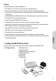
GET CONNECTED ENGLISH: DEUTSCH: ITALIANO: ESPAÑOL: Pg 1-28 Pg 29-56 Pg 57-84 Pg 85-112 BROADBAND WIRELESS ROUTER FRANÇAIS: Pg 113-140 : Pg 141-168 BAR-WL HUBS • SWITCHES • ADAPTERS • WIRELESS LAN • USB • KVMs • MEDIA CONVERTERS • ROUTERS
ENGLISH Table of Contents Technical Specifications FCC Interference Statement CE Declaration of Conformity Features of the BAR-WL Wireless Router 2 3 3 3 1. 1.1 1.2 1.3 1.4 1.5 1.6 Installing the BAR-WL Wireless Router Package Contents Front Panel LEDs Rear Panel & Connections Before connecting your BAR-WL Wireless Router Computer System Requirements and Setup Installing the BAR-WL Wireless Router 3 3 5 5 6 7 7 2. 2.1 2.2 2.3 2.3.1 2.3.2 2.3.3 2.4 2.5 2.6 2.7 2.8 2.9 2.10 2.11 2.12 2.12.1 2.12.2 2.12.
TECHNICAL SPECIFICATIONS Dimensions 175mm (L) x 117mm (W) x 32mm (H) Output Power 18dBm (average) Weight 378g Receiving Sensitivity 84dBm@11M Interface Ports 1 x RJ45 10BaseT/100BaseTX WAN port (Auto MDI/MDIX) 4 x RJ45 10BaseT/100BaseTX LAN ports (Auto MDI/MDIX) Coverage Area Indoors: Up to 50M (165 ft.) @ 11Mbps Up to 80M (265 ft.) @ 5.5Mps or lower Standards Compliance IEEE 802.3 10BASE-T IEEE 802.3u 100BASE-TX IEEE 802.11b Wireless IEEE 802.3x Flow control Outdoors: Up to 150M (500 ft.
REGULATORY COMPLIANCE FCC Interference Statement This device complies with Part 15 of FCC rule. Operation is subject to the following two conditions: • This device may not cause harmful interference. • This device must accept any interference received, including interference that may cause undesired operation. This Broadband Wireless Router has been tested and found to comply with the limits for a Class B digital device, pursuant to Part 15 of the FCC Rules.
Features Your BAR-WL Wireless Router provides the following features: • Allows multiple users to access Internet at the same time using a single public IP Address. • Allows users on Ethernet LAN and wireless LAN to transfer data to each other through wireless-to-wire bridge. • Provides wireless access roaming, best access point selection, loading balance, network traffic filtering included in wireless roaming function.
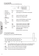
1.2 Front Panel LEDs The following figure shows the front view of the BAR-WL Wireless Router. WLAN WAN LAN 100M Link Link/Act Power Act Col/Fdx 1 2 3 4 • PWR (Power) Green Steady on when power is on. • DIAG (Diagnostic) Red Light up during power on self-check. Not lit in normal operation. Enable: Green Steady on when AP (Access Point) is enabled. Activity: Green Blinking when data is following through AP.
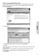
1.4 Before connecting your BAR-WL Wireless Router Before you connect your BAR-WL Wireless Router, Corega recommend that you download installation instructions particular to your ISP from the Corega website. These instructions will inform you how to configure the BAR-WL to work with your ISP. www.corega-international.com ENGLISH Select the knowledge base • Enter BAR-WL in the Sub-product category, and the name of your ISP in the Search Text field. • Press ‘Search’.
1.5 Computer System Requirements and Setup To connect to the Internet, an external ADSL or Cable modem and an Internet access account from an ISP are required. In order to operate with the BAR-WL Wireless Router, each PC that is to be connected should have the following things installed: • Ethernet NIC (Network Interface Card: a 10Base-T or 10/100Base-T/TX Ethernet card), or wireless client card for wireless connection. • System OS: Windows 95, Windows 98, Windows NT4.0, or Windows 2000, or Windows XP.
Provided by some ISPs Host Name: Domain Name: IP address given by ISP: Dynamic IP Address Fixed (Static) IP Address: Subnet Mask: Default Gateway: DNS Server Primary: DNS Server Secondary: DNS Server Third: PPP authentication: Login Name: Password: WAN Connection Type: Dynamic IP (DHCP): Fixed (Static ) IP: PPPoE: Your Broadband Wireless Router is designed to use a Web-based Graphical User Interface for configuration. Bring up your web browser and type http://192.168.1.
2.3 Initial Configuration – Setup The “OnePage Setup” screen is the first screen you will see when you access the Router Configuration Wizard. If the router has already been successfully installed and set up, this screen’s values will already be properly configured. From the “OnePage Setup” screen, the user needs to select the operating mode of the WAN connection of the router.
• ESSID (Extend Service Set Identifier) ESSID is the unique name shared among all clients and the BAR-WL Wireless Router in a same wireless network. The ESSID must be identical for all wireless devices and must not exceed 32 characters. The default value for the ESSID is ‘corega’. • Channel Select the appropriate channel number from the drop-down. The permissible channels are different from Regulatory Domains. Make sure that all points in the same wireless network use the same channel.
2.3.2 OnePage Setup with Static IP on the WAN ENGLISH In this mode, the Public IP Address and Subnet Mask of the router are used by external users of the Internet (including your ISP). • Specify WAN IP Address Enter the IP address provided by your ISP. • Subnet Mask Enter the subnet mask values provided by your ISP. • Default Gateway IP Address Your ISP will provide you with the Default Gateway IP Address. This is sometimes called the ‘Next-hop’.
2.3.3 OnePage Setup with PPPoE on the WAN PPPoE is a dial-up type connection type provided by some ISPs. Note that if you select PPPoE, please remove any existing PPPoE applications on any PCs on your LAN. • Password Enter the password your ISP provide to you. ENGLISH • User Name Enter the user name your ISP provide to you. • Connect-on-demand Is a utility to trigger the PPPoE session when it is on disconnection status and there is packet being going out through WAN port.
2.4 Device Administration Settings ENGLISH This feature allows the administrator to manage the router by setting certain parameters. For security reasons, it is strongly recommended that you set the Password so that only authorized persons are able to manage this router. If the Password is left blank, all users on your network can access this router simply by entering the unit’s IP Address into their web browser’s location window.
2.5 Wireless This setting page allows you to configure more advanced wireless functions. • TX Rates Select either 1~2 Mbps or 1~2~5.5~11Mbps auto fallback. • Station MAC Filter The router can block non-specific MAC addresses from connecting via the wireless LAN. To enable this filter, select ‘Enable’. ENGLISH • Authentication Type Select either Open System or Share Key as authentication type. If you are not sure, select Auto.
2.6 DHCP Configuration ENGLISH A DHCP (Dynamic Host Configuration Protocol) Server can automatically assign IP Addresses to each computer in your network on the LAN ports. Unless you already have a DHCP Server in you LAN, it is highly recommended that you set your router to act as a DHCP server. • Dynamic Server Select “Enable” to use the DHCP server option of the router. If you already have a DHCP server in your network, set the router's DHCP option to “Disable”.
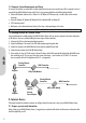
2.7 Static Routing Only users with an excellent understanding of router protocols should attempt to change settings in this area. • Select Route entry Select the route entry number from 1 to 5 that you wish to configure. Router Local LAN A 192.168.1.0 Internet BAR WL Local LAN B containing destination address 192.168.2.0 Default Gateway address 192.168.1.2 • Destination LAN IP and Subnet Mask Enter the IP Address and Subnet Mask of the destination LAN that the immediate LAN is to communicate with.
2.8 DDNS ENGLISH This feature allows the router to register with a Dynamic Domain Name Server. This allows the user to host web server etc, without a fixed IP address. • DDNS Services Check ‘Enable’ if you wish to use this funtion. Default is ‘Disable’ • User Name Enter your User Name provided by your DDNS provider. • Password Enter your Password provided by your DDNS provider. • Host Name Enter the your Host Name that remote users on the Internet will use to access your services.
2.9 Virtual Server The Virtual Server Settings application allows you to set up to ten public services, such as a Web Address, Email, FTP etc. that can be accessed by external users of the Internet. Each service is provided by a dedicated network computer (server) configured with a fixed (static) IP Address.
Here lists the protocol and port ranges that used by some common application. Application FTP Server Half Life MSN Messenger Quake 2 Quake III Protocol TCP UDP TCP TCP UDP UDP UDP TCP TCP UDP UDP UDP Telnet Server Web Server TCP TCP PC Anywhere host Port Range 21 6003, 7002, 27010, 27015, 27025 6891-6900 (File-send) 1863 1863 5190 6901 (Voice) 6901 (Voice) 5631 5632 27910 27660 (first player) "C:\Program Files\Quake III Arena\quake3.exe" +set net_port 27660 27661 (second player) 23 80 ENGLISH 2.
• Outgoing Port Range Enter the port number or range numbers this application uses when it sends packets outbound. The Outgoing Control Port Numbers act as the trigger. When the BAR-WL Wireless Router detects the outgoing packets with these port numbers, it will allow the inbound packets with the Incoming Port Numbers that you set in the next column to pass through the BAR-WL Wireless Router. • Incoming Control Enter the port number or range numbers the inbound packets carry.
1. Before setting up a LAN PC to act as a DMZ Host, configure it with a fixed IP Address. 2. In the “One Page Setup” screen, ensure the Private IP Address is set to the BAR-WL Wireless Router’s default setting of 192.168.1.1. In the Public IP Address area, select “Specify an IP Address”, then enter the IP Address and other necessary information provided by your ISP. 3. Click “DMZ Host” from the Advanced Menu. Enter the fixed IP Address of the Exposed Host PC in the “DMZ Host” IP Address location.
Here is an example of the IP Access Setting. Enter the range of 51~80 in the Filter Group column and 20~80 in the Block port Range column, then click “Apply” button. As the result, the user’s computers which have IP Addresses in the range of 192.168.1.51 to 192.168.1.80 will not be able to use the applications which use port numbers from 20 to 80, such as FTP, Telnet and web browsing. 2.12.
2.12.3 MAC Address Filter ENGLISH • Enter the MAC addresses that you want to filter (not allow access) into the table. Click ‘Apply’ when complete. Up to 50 MAC addresses can be filtered. 23 2.13 Status Monitor This screen shows the status of the BAR-WL Wireless Router.
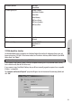
Appendix A.1 Installing the TCP/IP Protocol If you are not sure whether the TCP/IP Protocol have been installed, follow these steps to check, and if necessary, to install TCP/IP onto your PCs. 1. Click the “Start” button. Choose “Settings”, then “Control Panel”. Double-click the “Network” icon. Your Network window should appear. ENGLISH Select the “Configuration” tab. Note: For Windows 2000 & Windows XP Setting Click the “Local Area Connection” icon on the right bottom side of your desktop screen.
ENGLISH There is only one tab “General” in the Network window. 25 2. Check whether the TCP/IP Protocol have already been installed onto your computer’s Ethernet card. Note that TCP/IP Protocol can be installed for a computer’s Dial-Up Adapter as well as for the Ethernet card. - If yes, go to step 7. - If no, click the “Add” button.
3. Double-click “Protocol” on the Select Network Component Type or highlight “Protocol” then click “Add”. 4. Highlight “Microsoft” under the list of manufacturers. Double-click “TCP/IP” from the list on the right or highlight “TCP/IP” then click “OK” to install TCP/IP. ENGLISH 5. After a few seconds, you will be brought back to the Network window. The TCP/IP Protocol should now be on the list of installed network components (see 2 above). 6. Click the “Properties” button.
7. Select “Obtain an IP address automatically”. Click “OK”. Restart your PC to complete the TCP/IP installation. ENGLISH Appendix A.2 Fixed (Static) IP Addresses Configuration Fixed (Static) IP addresses may be assigned to network devices for many reasons, such as the server PCs or printers which are consistently accessed by multiple users. To set up computers with Fixed (Static)IP Addresses, go to the “IP Address” tab of the “TCP/IP Properties” window as showing above. 1.
2. Select “Enable DNS” in the “DNS Configuration” tab and enter the “DNS IP Address” obtained from your ISP in the “Server Search Order” location. Click “OK”. ENGLISH 3. Click “Gateway” tab and enter the Broadband Wireless Router’s default gateway value 192.168.1.1 in the “New gateway” field, then click “Add” Button. 4. Click “OK”. Restart your PC to complete the TCP/IP installation.
DEUTSCH Inhalt Technische Daten FCC Interference Statement CE-Emblem – Sicherheitshinweis Funktionsmerkmale 30 31 31 32 1. 1.1 1.2 1.3 1.4 1.5 1.6 Installation des BAR-WL Routers Packungsinhalt LEDs auf der Front des Geräts Geräterückseite und Anschlüsse Vor dem ersten Verbindungsaufbau Systemanforderungen und Setup Installation des BAR-WL Wireless Router 32 32 33 33 34 35 35 2. 2.1 2.2 2.3 2.3.1 2.3.2 2.3.3 2.4 2.5 2.6 2.7 2.8 2.9 2.10 2.11 2.12 2.12.1 2.12.2 2.12.3 2.
TECHNISCHE DATEN Größe 175 (L) x 117 (B) x 32 (H) mm Datensicherheit Ermöglicht 64-bit und 128-bit WEP Verschlüsselung. Gewicht 378g Sendeleistung 18dBm Netzwerksanschlüsse 1 x RJ45 10BaseT/100BaseTX WAN port (Auto MDI/MDIX) 4 x RJ45 10BaseT/100BaseTX LAN ports (Auto MDI/MDIX) Empfangsempfindlichkeit 84dBm@11M Unterstützte Standards IEEE 802.3 10BASE-T IEEE 802.3u 100BASE-TX IEEE 802.11b Wireless IEEE 802.3x Flow control Reichweite In Räumen: Bis zu 50m (165 ft.) bei 11Mbps Bis zu 80m (265 ft.
RICHTLINIENKONFORMITÄT FCC Interference Statement Diese Ausrüstung wurde geprüft und als konform mit den Richtlinien für ein digitales Gerät der Klasse B entsprechend Teil 15 der FCC-Richtlinien befunden. Diese Richtlinien dienen dem angemessenen Schutz gegen Funkstörungen bei der Installation im Wohnbereich. Diese Ausrüstung erzeugt und verwendet Funkfrequenzenergie und kann diese ausstrahlen. Ihre nicht dieser Anleitung entsprechende Installation und Verwendung kann Störungen des Funkverkehrs verursachen.
Funktionsmerkmale Ihr BAR-WL Wireless Router ermöglicht: • Mehreren Benutzern die Nutzung einer einzigen öffentlichen IP-Addresse zur selben Zeit. • Kommunikation zwischen Etherrnet-LAN und Wireless-LAN über eine “wireless-to-wire bridge”. • Unterbreichungsfreie Wireless-Anbindung, automatische Auswahl des besten Access Points, Paketflusskontrolle sowie Netwerksfilterung • 64 bit / 128 bit WEP-Verschlüsselung (Wired Equivalent Privacy) für sichere Wireless-Verbindungen. • Vollständige Unterstützung von 802.
1.2 LEDs auf der Front des Geräts Die folgende Grafik zeigt eine Frontansicht des BAR-WL Wireless Routers. WLAN WAN LAN 100M Link Link/Act Power Act Col/Fdx 1 2 3 4 • PWR (Power) Grün Leuchtet bei Spannungsversorgung • DIAG (Diagnose) Rot Leuchtet während des Selbsttests. Leuchtet nicht im normalen Betrieb. Bereitschaft: Grün Leuchtet wenn ein Access Point verfügbar ist. Aktivität: Grün Blinkt, wenn Daten über das Wireless LAN transferiert werden.
1.4 Vor dem ersten Verbindungsaufbau Corega empfielt den Download Provider-spezifischer Informationen und Installationsanweisungen von der Corega-Website vor dem ersten Verbindungsaufbau mit dem BAR-WL. Diese Anleitungen beschreiben im Detail die Konfiguration bestimmter Providereinstellungen. www.corega-international.com DEUTSCH Wählen Sie links unten als Sprache “Deutsch”. Klicken Sie dann unter “Support / Drivers” die “datenbank” an.
1.5 Systemanforderungen und Setup Um eine Verbindung mit dem Internet herzustellen, wird ein ADSL- oder Kabelmodem, sowie ein gültiger Account bei einen Provider benötigt. Um den Router effektiv zu nutzen sollte jeder Computer folgendes unterstützen: • Ethernet Netzwerkskarte (10Base-T oder 10/100Base-T/TX) oder Wireless-Netzwerksanbindung • Betriebssystem: Windows 95, Windows 98, Windows NT4.0, Windows 2000, oder Windows XP. • TCP/IP Netwerksprotokoll. • Internet-Browser, zum Beispiel Netscape Navigator 6.
Bereitgestellt von einigen Providern: Host Name: Domain Name: Vom Provider zugewiesene IP-Addresse: Dynamische IP-Addresse: Statische (fixe) IP-Addresse: Netzwerksmaske: Default Gateway: DNS-Server Primary: DNS-Server Secondary: DNS-Server Third: Zugangsdaten: Benutzername: Passwort: WAN-Verbindungstyp: Dynamische IP (DHCP): Statische IP: PPPoE: Ihr Router bietet Ihnen eine Web-Basierte graphische Oberfläche für die Konfiguration. Starten Sie einen Web-Browser, und tippen Sie http://192.168.1.
2.3 Basiskonfigiuration – Setup Die “OnePage Setup”-Seite ist die erste Seite die Sie sehen, wenn Sie auf die Router-Konfiguration zugreifen. Falls der Router bereits korrekt eingerichtet wurde, stimmen die Angaben auf dieser Seite. In der “OnePage Setup”-Seite müssen Sie die Betriebsart des WAN-Anschlusses auswählen. Sie haben die Wahl zwischen: • DHCP • Static (Fixed) IP • PPPoE Falls Sie nicht wissen welcher Eintrag erforderlich ist, kontaktieren Sie Ihren Internetprovider. DEUTSCH 2.3.
• ESSID (Extend Service Set Identifier) Die ESSID ist der Name des Wireless-Netzwerks, der auf allen Wireless-Geräten die untereinander kommunizieren wollen gleich sein muss. Er darf nicht länger als 32 Zeichen sein. Standardwert ist “corega”. • Channel Wählen Sie einen Kanal aus dem Dropdownmenü. Die Anzahl wählbarer Kanäle variiert nach Region. Alle Wireless-Geräte die miteinander kommuniezieren sollen, müssen den selben Kanal gewählt haben.
2.3.2 “OnePage Setup” mit statischer WAN-IP-Addresse DEUTSCH In dieser Betriebsart werden IP-Addresse und Netzwerksmaske des Routers fix festgelegt. • WAN IP Address Geben Sie hier die IP-Addresse ein, die Ihnen Ihr Proivder zur Verfügung stellt. • Subnet Mask Geben Sie hier die Netzwerksmaske ein, die Ihnen Ihr Provider zur Verfügung stellt. • Default Gateway IP Address Geben Sie hier die IP-Addresse des Gateways ein, den Ihnen Ihr Provider zur Verfügung stellt. Auch als “Next Hop” bekannt.
2.3.3 “OnePage Setup” mit PPPoE-WAN-Verbindungen PPPoE ist eine Einwahlmethode, die einige (ADSL-) Provider anbieten. Falls Sie PPPoE einrichten, entfernen Sie bitte vorhandenen PPPoE Einwahlprogramme von den PCs ihres Netzwerks, um Konflikte zu vermeiden. • Password Geben Sie hier Ihr Einwahlpasswort ein. DEUTSCH • User Name Geben Sie hier Ihren Einwahlbenutzernamen ein.
2.4 “Device Administration Settings” - Einstellungen für die Gerätekonfiguration DEUTSCH Diese Funktion erlaubt die Einrichtung des Routers auf einigen sicherheitsrelevanten Gebieten. Um Sicherheit zu gewährleisten, empfehlen wir Ihnen ein Passwort einzustellen, um zu verhinden, dass nicht autorisierte Personen Änderungen am Router vornehmen. Falls kein Passwort eingestellt ist, kann jeder im Netzwerk durch einfaches Eingeben der IP-Addresse auf die Router-Konfiguration zugreifen.
2.5 Wireless Diese Seite ermöglicht Ihnen eine erweiterte Konfiguration der Wireless-Funktionen. • TX Rates Wählen Sie die gewünschte Datentransferrate aus der Liste aus (1-2 Mbit, 1, 2, 5.5, 11 Mbit oder auto fallback). • Station MAC Filter Der Router kann nicht-spezifizierten MAC-Addressen den Zugriff verweigern. Falls Sie diese Art der Sicherung wünschen, wählen Sie “Enable”. DEUTSCH • Authentication Type Wählen Sie “Open System” oder “Share Key” als Autentifikation.
2.6 “DHCP Settings” - DHCP-Konfiguration DEUTSCH Ein DHCP (Dynamic Host Configuration Protocol) Server kann den Computern auf den LAN-Ports automatisch die korrekten Netwerkseinstellungen zuweisen. Solange nicht bereits einen DHCP-Server im Netwerk vohanden ist, sollten Sie den eingebauten DHCP-Server des Routers aktivieren. • Dynamic Server Wählen Sie “Enable” um den DHCP-Server zu aktivieren. Falls Sie bereits einen DHCP-Server im Netzwerk betreiben, setzen Sie diese Option auf “Disable”.
2.7 “Static Routing” – Statisches Routing Diese Einstellungen sollten nur von Personen mit tieferem Wissen über Routing verstellt werden. • Select Route entry Wählt den Routingeintrag 1 – 5 den Sie konfigurieren möchten. Local LAN A 192.168.1.0 Internet BAR WL Local LAN B containing destination address 192.168.2.0 DEUTSCH Router Default Gateway address 192.168.1.2 • Destination LAN IP und Subnet Mask Tragen Sie hier das IP.
2.8 DDNS DEUTSCH Diese Funktion ermöglicht die Nutzung dynamischer Domain-Namen. Dies erlaubt zum Beispiel den Betrieb eines Webservers ohne statische IP-Addresse. • DDNS Services Wählen Sie auf ‘Enable’ um DDNS zu aktivieren. Standard ist ‘Disable’ • User Name Tragen Sie hier den Benutzernamen für die DDNS-Aktualisierung ein. • Password Tragen Sie hier das Passwort für die DDNS-Aktualisierung ein. • Host Name Tragen Sie hier den Hostnamen ein, unter dem Ihre Dienste erreichbar sein sollen.
2.9 Virtual Server Die Virtual-Server-Funktion ermöglicht Ihnen die Freigabe von bis zu 10 Diensten des LAN, wie Web-, Mail- oder FTP-Server für den Zugriff aus dem Internet. Jeder Computer, dessen Netzwerksdienst von Aussen erreichbar sein soll, muss mit einer statischen IPAddresse ausgestattet sein (keine automatische DHCP-Konfiguration).
Hier ist eine Liste der Ports die einige Programme verwenden. Programm FTP Server Half Life MSN Messenger Quake 2 Quake III Protokoll TCP UDP TCP TCP UDP UDP UDP TCP TCP UDP UDP UDP Telnet Server Web Server TCP TCP PC Anywhere host Verwendete Ports 21 6003, 7002, 27010, 27015, 27025 6891-6900 (Dateien versenden) 1863 1863 5190 6901 (Sprachübertragungen) 6901 (Sprachübertragungen) 5631 5632 27910 27660 (erster Spieler) "C:\Program Files\Quake III Arena\quake3.
• Outgoing Port Range Tragen Sie die Port-Nummer oder den Port-Bereich ein, über den die Anwendung Daten versendet. Diese Ports werden als “Trigger” verwendet. Wenn der Router feststellt das über diese Ports Datenpakete versendet werden, ermöglicht der Router den Empfang von Daten über die in “Incoming Control” eingetragenen Ports. • Incoming Control Tragen Sie die Port-Nummer oder den Port-Bereich ein, über den eingehendende Daten verwertet werden sollen.
1. Bevor Sie einen LAN-Computer mit der DMZ-Funktion ausstatten, müssen Sie ihm eine statische IP-Addresse zuweisen. 2. Stellen Sie sicher das sich die Private IP-Addresse des Routers, auf der “One Page Setup”-Seite, in der Standardeinstellung 192.168.1.1 befindet. Im Bereich für die öffentliche IP-Addresse (Public ip address) wählen Sie “Specify an IP Address”, und tragen Sie dort die IP-Addresse und andere erforderliche Informationen, die Ihnen Ihr Provider zugewiesen hat, ein. 3.
Ein Beispiel für die IP-Zugrifsseinstellungen: Tragen Sie als Port-Bereich 51 bis 80 in die “Filter Grop”-Spalte und 20 bis 80 in die “Port Range”-Spalte ein und klicken Sie dann auf “Apply”. Das Resultat ist, dass Computer im LAN, deren IP-Addresse im Bereich von 192.168.1.51 bis 192.168.1.80 liegt, auf Internet-Dienste wie Web-, FTP-Server und Telnet-Server nicht mehr zugreifen können. 2.12.
2.12.3 Filder für MAC-Addressen (MAC Address Filter) DEUTSCH • Tragen Sie die MAC-Addressen ein, denen der Zugriff auf den Router verweigert werden soll. Klicken Sie auf “Apply” um die Änderungen zu speichern. Es können bis zu 50 MAC-Addressen eingetragen werden 51 2.13 Statusanzeige (Status Monitor) Diese Seite zeigt den Zustand des BAR-WL Routers.
Anhang A.1 Installation des TCP/IP Protokolls Falls Sie sich nicht sicher sind, ob Sie das TCP/IP Protokoll installiert haben, folgen Sie dieser Anleitung zur Prüfung und ggf. zur Installation von TCP/IP auf ihren Computer. 1. Klicken Sie auf “Start”, wählen Sie “Einstellungen”, dann “Systemsteuerung”. Doppelklicken Sie auf das “Netzwerk”-Symbol. Ein Netzwerksfenster wird erscheinen. DEUTSCH Wählen Sie den Abschnitt “Konfiguration”.
DEUTSCH Dort befindet sich als einzige Auswahl “Allgemein”. 53 2. Prüfen Sie ob das TCP/IP Protokoll bereits für die Ethernet-Netzwerkskarte installiert wurde. Bedenken Sie bitte, dass das TCP/IP Protokoll auch für andere Verbindungen (z.B. Einwahlverbindungen) als Ethernet installiert sein kann - Falls ja, fahren Sie mit Schritt 7 fort. - Falls TCP/IP noch nicht installiert ist, klicken Sie auf “Hinzufügen”.
3. Doppelklicken Sie auf “Protokoll”, oder wählen Sie “Protokoll” und klicken Sie auf “Hinzufügen”. 4. Wählen Sie “Microsoft” aus der Herstellerliste. Doppelklicken Sie auf “TCP/IP” in der rechten Liste, oder wählen Sie “TCP/IP” und klicken Sie auf “OK” um die Installation abzuschliessen. DEUTSCH 5. Nach einigen Sekunden befinden Sie sich wieder im Netzwerksfenster. Das TCP/IP-Protokoll sollte nun in der Liste aufscheinen. 6.
7. Wählen Sie “IP-Addresse automatisch beziehen” und klicken Sie auf OK. Starten Sie Ihren Computer neu um die Installation abzuschliessen. DEUTSCH Anhang A.2 Konfiguration einer statischen IP-Addresse 55 Es gibt verschiedene Gründe um einem Computer eine statische IP-Addresse zuzuweisen, zum Beispiel Server- oder DMZ-Betrieb. Um dem Computer eine statische IP-Addresse einzustellen, gehen Sie in den “IP-Addresse”-Tab der “TCP/IP Einstellungen” wie unten gezeigt. 1.
2. Wählen Sie “DNS aktivieren” im “DNS -Konfiguration”-Tab und geben Sie die DNS-IP-Addresse(n), die Ihnen Ihr Provider zugewiesen hat in das “DNS-Suchreinfolge”-Feld ein. Klicken Sie dann auf “OK”. DEUTSCH 3. Wählen Sie den “Gateway”-Tab und tragen Sie die IP-Addresse des BAR-WL Routers in das “Neuer Gateway”-Feld ein und klicken Sie dann auf “Hinzufügen”. 4. Klicken Sie auf “OK”. Starten Sie den Computer neu um die TCP/IP-Installation abzuschliessen.
ITALIANO Sommario Specifiche tecniche Avviso FCC sulle interferenze Dichiarazione di conformità CE Caratteristiche del router wireless BAR-WL 58 59 59 59 1. 1.1 1.2 1.3 1.4 1.5 1.6 Installing the BAR-WL Wireless Router Package Contents Front Panel LEDs Rear Panel & Connections Before connecting your BAR-WL Computer System Requirements and Setup Installazione del router wireless BAR-WL 59 59 61 61 62 63 63 2. 2.1 2.2 2.3 2.3.1 2.3.2 2.3.3 2.4 2.5 2.6 2.7 2.8 2.9 2.10 2.11 2.12 2.12.1 2.12.2 2.12.3 2.
SPECIFICHE TECNICHE Dimensioni 175 (lung.) x 117 (larg.) x 32 (alt.) mm Potenza di uscita 18dBm Peso 378 g Sensibilità in ricezione 84dBm@11M Porte interfaccia 1 porta WAN RJ45 10BaseT/100BaseTX (MDI/MDIX automatico) 4 porte LAN RJ45 10BaseT/100BaseTX (MDI/MDIX automatico) Area di copertura In ambiente chiuso: Fino 50 m @ 11 Mbps Fino a 80 m @ 5,5 Mbps (o inferiore) All'aperto: Fino 150 m @ 11 Mbps Fino a 300 m @ 5,5 Mbps (o inferiore) (in base al tipo di ambiente) Conformità agli standard IEEE 802.
INFORMAZIONI DI CONFORMITÀ Avviso FCC sulle interferenze Questo dispositivo è conforme con la Parte 15 della normativa FCC. Il suo utilizzo è soggetto alle due condizioni seguenti: • Il dispositivo non deve causare interferenze nocive. • Il dispositivo deve accettare qualsiasi interferenza ricevuta, comprese quelle che potrebbero causare problemi nel suo funzionamento.
Caratteristiche del router wireless BAR-WL 1. 1. Installazione del router wireless BAR-WL ITALIANO Il router wireless BAR-WL presenta le seguenti caratteristiche: • Accesso a Internet da parte di più utenti contemporaneamente, tramite un unico indirizzo IP pubblico. • Trasferimento di dati tra utenti di reti LAN Ethernet e LAN wireless tramite adattatori wireless-to-wire.
1.2 Indicatori del pannello anteriore La figura seguente mostra il pannello anteriore del router wireless BAR-WL. WLAN WAN LAN 100M Link Link/Act Power Act Col/Fdx 1 2 3 4 • PWR (Alim.) Verde Accesa e fissa quando il router è acceso. • DIAG (Diagnostica) Rossa Si accende durante l’autotest di accensione. È spenta durante il normale funzionamento. Enable (Abilita): Verde Accesa e fissa quando viene abilitato un punto di accesso (AP).
1.4 Prima di collegare il router BAR-WL Prima di collegare il router BAR-WL, si consiglia di scaricare dal sito web Corega le istruzioni di installazione specifiche per il proprio ISP (Internet Service Provider, provider Internet). Grazie a queste istruzioni sarà possibile configurare il router BAR-WL per il proprio ISP. www.corega-international.
1.5 Requisiti e configurazione del computer Per connettersi a Internet, sono necessari un modem esterno ADSL o via cavo e un account Internet presso un ISP. Per poter funzionare con il router di accesso a banda larga, ogni PC da collegare deve avere i seguenti requisiti: • Scheda di rete Ethernet (10Base-T o 10/100Base-T/TX) o scheda client senza fili per connessioni wireless • Sistema operativo: Windows 95, Windows 98, Windows NT4.0, Windows 2000 o Windows XP.
Dati forniti da alcuni ISP Nome host: Nome dominio: Indirizzo IP assegnato dall’ISP Indirizzo IP dinamico Indirizzo IP fisso (statico) Subnet mask: Gateway predefinito: Server DNS principale: Server DNS secondario: Terzo server DNS: Autenticazione PPP: Nome di login: Password: Tipo di connessione WAN IP dinamico (DHCP) IP fisso (statico) PPPoE Il router wireless a banda larga BAR-WL è progettato per utilizzare un’interfaccia utente di tipo web per la configurazione.
2.3 Configurazione iniziale Nel momento in cui si accede alla configurazione guidata del router, viene visualizzata la schermata OnePage Setup. Se il router è già stato installato e configurato, i valori visualizzati sono già impostati. Dalla schermata OnePage Setup, selezionare la modalità operativa della connessione WAN del router.
• Channel Selezionare il numero di canale appropriato dall’elenco a discesa. I canali ammessi variano in base alle disposizioni di legge. Verificare che tutti i punti di accesso di una rete wireless utilizzino lo stesso canale. • WEP (Wired Equivalent Privacy) Standard di crittografia utilizzato per proteggere le comunicazioni di dati senza fili.
2.3.2 OnePage Setup con connessione WAN tramite IP statico ITALIANO Se si seleziona questo tipo di connessione, l’indirizzo IP pubblico e la subnet mask del router vengono utilizzati dagli utenti Internet esterni (compreso l’ISP). • WAN IP Address Specificare l’indirizzo IP fornito dall’ISP. • Subnet Mask Inserire i valori di subnet mask forniti dall’ISP. • Default Gateway IP Address Indirizzo IP del gateway predefinito fornito dall’ISP.
2.3.3 OnePage Setup con connessione WAN PPPoE Viene definita PPPoE un tipo di connessione di “accesso remoto” fornita da alcuni ISP. Se si seleziona la connessione PPPoE, è necessario rimuovere eventuali applicazioni PPPoE esistenti dai PC della rete LAN. • Password Specificare la password fornita dall’ISP. ITALIANO • User Name Specificare il nome utente fornito dall’ISP.
2.4 Amministrazione del dispositivo ITALIANO La funzione Device Administration Settings consente all’amministratore di specificare alcuni parametri di gestione del router. Per motivi di sicurezza, si raccomanda di impostare una password di protezione che consenta la gestione del router solo da parte di personale autorizzato. Se il campo Password viene lasciato vuoto, tutti gli utenti possono accedere al router, semplicemente specificando l’indirizzo IP dell’unità nella finestra Indirizzo del browser web.
2.5 Wireless Questa schermata di impostazione consente di configurare funzioni wireless avanzate. • TX Rates Selezionare 1~2 Mbps o 1~2~5.5~11Mbps con fallback automatico. • Station MAC Filter Il router è in grado di bloccare indirizzi MAC non specifici per impedirne la connessione alla rete LAN wireless. Per attivare questa funzione di filtro, selezionare Enable. ITALIANO • Authentication Type Selezionare un tipo di autenticazione tra Open System e Share Key. In caso di dubbi, selezionare Auto.
2.6 Configurazione DHCP ITALIANO Un server DHCP (Dynamic Host Configuration Protocol) può assegnare automaticamente gli indirizzi IP a tutti i computer della rete collegati alle porte LAN. A meno che non sia già presente un server DHCP nella rete locale, si consiglia di impostare il router come server DHCP. • Dynamic Server Selezionare Enable per utilizzare l’opzione “server DHCP” del router. Se è già presente un server DHCP nella rete, impostare l’opzione DHCP del router su Disable.
2.7 Routing statico Le impostazioni di questa sezione devono essere configurate solo dagli utenti che conoscono molto bene i protocolli del router. • Select Route entry Selezionare la voce di routing da configurare (da 1 a 5). Local LAN A 192.168.1.0 Internet BAR WL Local LAN B containing destination address 192.168.2.0 ITALIANO Router Default Gateway address 192.168.1.
2.8 DDNS ITALIANO Questa funzione consente al router di registrarsi presso un server DDNS (Dynamic Domain Name Server), per permettere all’utente di fungere da host per server web ecc., senza la necessità di un indirizzo IP fisso. • DDNS Services Selezionare Enable per attivare la funzione. L’impostazione predefinita è Disable. • User Name Inserire il nome utente fornito dal provider DDNS. • Password Inserire la password fornita dal provider DDNS.
2.9 Server virtuale La schermata Virtual Server Settings consente di configurare fino a dieci servizi pubblici, quali indirizzo web, posta elettronica, FTP ecc., accessibili da utenti esterni collegati a Internet. Ciascun servizio viene fornito da un computer di rete dedicato (server), configurato con un indirizzo IP fisso (statico).
Segue un elenco di protocolli e numeri di porta utilizzati da alcune tra le applicazioni più diffuse. Applicazione Server FTP Half Life MSN Messenger Quake 2 Quake III Protocollo TCP UDP TCP TCP UDP UDP UDP TCP TCP UDP UDP UDP Server Telnet Server Web TCP TCP Host PC Anywhere Intervallo porte 21 6003, 7002, 27010, 27015, 27025 6891-6900 (invio file) 1863 1863 5190 6901 (voce) 6901 (voce) 5631 5632 27910 27660 (primo giocatore) "C:\Programmi\Quake III Arena\quake3.
• Outgoing Port Range Specificare il numero di porta o l’intervallo di porte utilizzato dall’applicazione per inviare pacchetti di dati in uscita. I numeri di porta assegnati per le trasmissioni in uscita fungono da attivatori. Se il router wireless a banda larga rileva un pacchetto di dati in uscita con uno di questi numeri di porta, esso consentirà al pacchetto di dati in entrata con uno dei numeri di porta specificati nella colonna Incoming Port Numbers di passare attraverso il router.
1. Prima di impostare un PC della rete LAN come host DMZ, assegnare al PC un indirizzo IP fisso. 2. Accedere alla schermata One Page Setup e verificare che in corrispondenza di Private IP Address sia impostato il valore 192.168.1.1, corrispondente all’indirizzo IP predefinito del router wireless a banda larga. Nell’area destinata all’indirizzo IP pubblico, selezionare Specify an IP address e specificare l’indirizzo IP ed eventuali altre informazioni necessarie fornite dall’ISP 3.
Segue un esempio di impostazione del controllo degli accessi tramite indirizzo IP. Specificare l’intervallo 51~80 in corrispondenza della colonna Filter Group e 20~80 in corrispondenza della colonna Block port Range, quindi fare clic su Apply. I PC con un indirizzo IP che rientra nell’intervallo 192.168.1.51-192.168.1.80 non saranno in grado di accedere alle applicazioni che utilizzano i numeri di porta da 20 a 80, quali FTP, Telnet e i browser web. 2.12.
2.12.3 Filtro indirizzi MAC ITALIANO • Specificare gli indirizzi MAC da filtrare (ai quali bloccare l’accesso). Al termine, fare clic su Apply. È possibile specificare fino a 50 indirizzi MAC. 79 2.
Appendice A.1 Installazione del protocollo TCP/IP Per verificare se il protocollo TCP/IP è già stato installato sui PC della rete ed, eventualmente, installarlo, procedere come segue. 1. Fare clic sul pulsante Start. Selezionare Impostazioni, Pannello di controllo. Fare doppio clic sull'icona Rete. Viene visualizzata la finestra di dialogo omonima. ITALIANO Selezionare la scheda Configurazione.
La finestra presenta un’unica scheda: Generale. ITALIANO 2. Verificare se il protocollo TCP/IP è già stato installato sulla scheda Ethernet del computer. Si rammenta che il protocollo TCP/IP può essere installato sia per l’adattatore di accesso remoto che per la scheda Ethernet del PC 81 - Se il protocollo è già installato, passare al punto 7. - In caso contrario, fare clic sul pulsante Aggiungi.
3. All’interno della finestra Selezione tipo di componente di rete, fare doppio clic su Protocollo oppure evidenziare Protocollo e fare clic su Aggiungi. 4. Selezionare Microsoft dall’elenco dei produttori. Fare doppio clic su TCP/IP nell’elenco visualizzato sulla destra, oppure evidenziare TCP/IP e fare clic su OK per installare il protocollo TCP/IP. ITALIANO 5. Dopo alcuni secondi, viene di nuovo visualizzata la finestra di dialogo Rete.
7. Selezionare Ottieni automaticamente un indirizzo IP. Fare clic su OK. Riavviare il PC per portare a termine l’installazione del protocollo TCP/IP. ITALIANO Appendice A.2 Configurazione di indirizzi IP fissi (statici) 83 È possibile assegnare indirizzi IP statici ai dispositivi di rete per varie ragioni; ad esempio, può essere necessario assegnare un indirizzo IP statico ai PC server o alle stampanti ai quali accedono costantemente numerosi utenti.
2. Selezionare Attiva DNS all’interno della scheda Configurazione DNS e specificare l’indirizzo IP DNS ottenuto dall’ISP all’interno del campo Ordine di ricerca server DNS. Fare clic su OK. . ITALIANO 3. Fare clic sulla scheda Gateway e specificare il valore predefinito del gateway del router wireless a banda larga 192.168.1.1 all’interno del campo Nuovo gateway, quindi fare clic su Aggiungi. 4. 4. Fare clic su OK. Riavviare il PC per portare a termine l’installazione del protocollo TCP/IP.
ESPAÑOL Índice Especificaciones Técnicas Declaración de Interferencias de la FCC (Comisión Federal de Comunicaciones De Ee. Uu.) Declaración de Conformidad CE Características del Router inalámbrico BAR-WL 86 87 87 87 1. 1.1 1.2 1.3 1.4 1.5 1.
ESPECIFICACIONES TÉCNICAS Dimensiones 175 (L) x 117 (A) x 32 (H) mm Potencia de salida 18dBm Peso 378 g Sensibilidad de recepción 84dBm@11M Puertos de interfaz 1 x puerto WAN RJ45 10BaseT/100BaseTX (Auto MDI/MDIX) 4 x puertos LAN RJ45 10BaseT/100BaseTX (Auto MDI/MDIX) Zona de cobertura En interiores: hasta 50 m @ 11 Mbps hasta 80 m @ 5,5 Mbps o inferior Conformidad con los estándares IEEE 802.3 10BASE-T IEEE 802.3u 100BASE-TX Inalámbrico IEEE 802.11b Control de flujo IEEE 802.
CONFORMIDAD CON LA NORMATIVA VIGENTE Declaración de interferencias de la FCC (Comisión Federal de Comunicaciones de EE. UU.) Este dispositivo cumple la Parte 15 de las normas de la FCC. El funcionamiento está sujeto a las dos condiciones siguientes: Este dispositivo puede causar interferencias perjudiciales. Este dispositivo debe aceptar cualquier interferencia que reciba, incluso aquellas que puedan ocasionar su funcionamiento incorrecto.
Características del router inalámbrico BAR-WL ESPAÑOL Las características principales del router inalámbrico BAR-WL, son las siguientes: • Permite acceder a Internet a varios usuarios simultáneamente usando una sola dirección IP pública. • Permite a los usuarios de redes LAN Ethernet y LAN inalámbricas transferir datos de una a otra a través de un puente de la red inalámbrica a la cableada.
1.2 LEDs del panel delantero La siguiente figura muestra la vista delantera del router inalámbrico BAR-WL. WLAN WAN LAN 100M Link Link/Act Power Act Col/Fdx 1 2 3 4 • PWR (Alimentación) Verde Encendido fijo, cuando la alimentación está conectada. • DIAG (Diagnóstico) Rojo Se enciende durante la realización de la prueba automática. Apagado durante el funcionamiento normal. Enable: Verde Encendido fijo cuando el AP (Punto de acceso) está activado.
1.4 Antes de conectar el router inalámbrico BAR-WL Antes de conectar el router inalámbrico BAR-WL, Corega le recomienda que descargue las instrucciones de instalación específicas para su ISP desde el sitio web de Corega. Estas instrucciones le indicarán cómo configurar el router inalámbrico BAR-WL para que funcione con su ISP. www.corega-international.com ESPAÑOL Seleccione la base de conocimiento.
1.5 Requisitos y configuración del equipo informático Para establecer la conexión con Internet se necesita un módem de cable o ADSL y una cuenta de acceso a Internet contratada con un ISP. Para poder utilizar el router de acceso de banda ancha, todos los PC que se van a conectar tienen que tener instalados los siguientes elementos: • Tarjeta interfaz de red, Ethernet NIC (Network Interface Card: una tarjeta Ethernet 10Base-T ó 10/100Base-T/TX), ó una tarjeta de cliente inalámbrico para conexión inalámbrica.
Facilitado por algunos ISP Nombre del servidor: Nombre del dominio: Dirección IP facilitada por el ISP: Dirección IP dinámica: Dirección IP fija (estática): Máscara de subred: Puerta de acceso predeterminada: Servidor DNS primario: Servidor DNS secundario: Servidor DNS terciario: Autenticación PPP: Nombre de usuario (Login): Contraseña: Tipo de conexión WAN IP dinámica (DHCP) Fixed (Static) IP [IP fija (estática)] PPPoE La configuración del router inalámbrico de banda ancha se realiza por medio de u
2.3 Configuración inicial La pantalla “OnePage Setup” [Configuración OnePage] es la primera que verá al acceder al Asistente de configuración del router. Si el router ya se ha instalado y configurado correctamente con anterioridad, estos valores de la pantalla ya estarán bien configurados. En la pantalla “OnePage Setup”, el usuario tiene que seleccionar el modo de funcionamiento de la conexión WAN del router.
• ESSID (Identificador de conjuntos de servicios extendidos) ESSID es el nombre exclusivo que comparten todos los clientes del router inalámbrico de banda ancha en la misma red inalámbrica. El ESSID tiene que ser idéntico para todos los dispositivos inalámbricos y no debe exceder de 32 caracteres. El valor predeterminado del ESSID es “corega”. • Channel [Canal] Seleccione el número adecuado de canal en el menú desplegable. Los canales admitidos varían de acuerdo la normativa vigente en materia de dominios.
2.3.2 OnePage Setup con Static IP en la WAN ESPAÑOL En este modo, la dirección IP pública y la máscara de subred del router son usadas por usuarios externos de Internet (incluido su ISP). • Specify WAN IP Address [Especificar dirección IP WAN] Introduzca la dirección IP que le haya proporcionado su ISP. • Subnet Mask [Máscara de subred] Introduzca los valores de máscara de subred que le haya proporcionado su ISP.
2.3.3 OnePage Setup con PPPoE en la WAN PPPoE es una conexión del tipo “marcado” que ofrecen algunos ISP. Tenga en cuenta que si selecciona PPPoE, tiene que eliminar todas las aplicaciones PPPoE existentes en cualquiera de los PC de la LAN. • Password [Contraseña] Introduzca la contraseña que le haya proporcionado su ISP. ESPAÑOL • User Name [Nombre de usuario] Introduzca el nombre de usuario que le haya proporcionado su ISP.
2.4 Configuración de la administración del dispositivo ESPAÑOL Esta función permite al administrador gestionar el router configurando ciertos parámetros. Por razones de seguridad, es altamente recomendable establecer la contraseña para que sólo las personas autorizadas puedan administrar este router. Si la contraseña se deja en blanco, todos los usuarios de la red pueden acceder a este router simplemente introduciendo la dirección IP del dispositivo en el cuadro de dirección de su explorador web.
2.5 Wireless [Funciones inalámbricas] Esta pantalla de configuración permite configurar más funciones inalámbricas. • TX Rates [Velocidades de transmisión] Seleccione 1- 2 Mbps, ó 1-2-5.5-11 Mbps de reserva automática. • Station MAC Filter [Filtro de estación MAC] El router puede impedir que determinadas direcciones MAC se conecten a la LAN inalámbrica. Para activar este filtro, seleccione “Enable” [Habilitar].
2.6 Configuración de DHCP ESPAÑOL Un servidor DHCP (Dynamic Host Configuration Protocol, protocolo de configuración dinámica de host) puede asignar automáticamente direcciones IP a los ordenadores de la red que estén conectados a los puertos LAN. Salvo en el caso de que tenga un servidor DHCP en la LAN, es muy recomendable configurar el router para que actúe como servidor DHCP. • Dynamic Server [Servidor dinámico] Seleccione “Enable” [Habilitar] para usar la opción de servidor DHCP del router.
2.7 Enrutamiento estático Solamente los usuarios con excelentes conocimientos de los protocolos del router deben intentar cambiar la configuración en esta sección. • Select Route entry [Selección de entrada de ruta] Seleccione el número de entrada de ruta comprendido entre 1 y 5 que desea configurar. Local LAN A 192.168.1.0 Internet BAR WL Local LAN B containing destination address 192.168.2.0 ESPAÑOL Router Default Gateway address 192.168.1.
2.8 DDNS ESPAÑOL Esta función permite al router registrarse con un servidor de nombres de dominios dinámicos. Esto permite al usuario utilizar un servidor web, etc. sin una dirección IP fija. • DDNS Services [Servicios DDNS] Seleccione el botón de opción “Enable” [Habilitar] si desea usar esta función. La opción predeterminada es “Disable” [Deshabilitar]. • User Name [Nombre de usuario] Introduzca el nombre de usuario que le haya proporcionado su proveedor de DDNS.
2.9 Servidor virtual La aplicación Virtual Server Settings [Configuración de servidor virtual] permite configurar hasta diez servicios públicos como dirección web, correo electrónico, FTP, etc., a los que pueden acceder los usuarios externos de Internet. Cada uno de estos servicios es provisto por un ordenador dedicado de la red (servidor) configurado con una dirección IP fija (estática).
La siguiente tabla contiene una relación de protocolos y rangos de puertos usados por algunas aplicaciones de uso frecuente. Aplicación Servidor FTP Half Life MSN Messenger Quake 2 Quake III Protocolo TCP UDP TCP TCP UDP UDP UDP TCP TCP UDP UDP UDP Servidor Telnet Servidor web TCP TCP PC Anywhere host Rango de puertos 21 6003, 7002, 27010, 27015, 27025 6891-6900 (Archivo-enviar) 1863 1863 5190 6901 (Voz) 6901 (Voz) 5631 5632 27910 27660 (primer jugador) "C:\Program Files\Quake III Arena\quake3.
• Outgoing Port Range [Rango de puerto de salida] Introduzca el número o rango de números de puertos que esta aplicación usa para enviar paquetes. Los números de control de puertos de salida actúan como elementos de activación. Cuando el router inalámbrico de banda ancha detecta los paquetes de salida en puertos con estos números, permitirá pasar a través del router a los paquetes entrantes con números de puertos de entrada que haya configurado en la siguiente columna.
1. Antes de configurar un PC de la LAN para que actúe como host DMZ, configúrelo con una dirección IP fija. 2. En la pantalla “One Page Setup”, compruebe que la opción “Private IP Address” [Dirección IP privada] está configurada con el valor predeterminado del router inalámbrico de banda ancha, 192.168.1.1.
A continuación, se incluye un ejemplo de configuración de acceso IP. Introduzca el rango de 51-80 en la columna Filter Group [Grupo de filtrado] y el rango 20-80 en la columna Block Port Range [Rango de puertos bloqueados], y luego haga clic en el botón “Apply” [Aplicar]. Una vez hecho lo anterior, el sistema no permitirá a los ordenadores de los usuarios cuyas direcciones IP están dentro del rango comprendido entre 192.168.1.51 y 192.168.1.
2.12.3 Filtrado por dirección MAC ESPAÑOL • Introduzca en la tabla las direcciones MAC que desea filtrar (es decir, a las que desea impedir el acceso). Haga clic en “Apply” [Aplicar] cuando haya terminado. Se pueden filtrar hasta 50 direcciones MAC. 107 2.13 Monitor de estado En esta pantalla se muestra el estado del router BAR-WL.
Apéndice A.1 Instalación del protocolo TCP/IP Si no tiene la seguridad de que el protocolo TCP/IP ya esté instalado, puede seguir el procedimiento que se indica a continuación para comprobar y, si es necesario, instalar el protocolo TCP/IP en los PC. 1. Haga clic en el botón “Inicio”. Elija “Configuración” y luego, “Panel de control”. Haga doble clic en el icono “Red”. Aparecerá la ventana de la red. ESPAÑOL Seleccione la ficha “Configuración”.
En la ventana “Estado de la conexión de área local”, haga clic en el botón “Propiedades”; aparecerá la ventana de la red. ESPAÑOL En la ventana Red, sólo aparece la ficha “General”. 109 2. Compruebe si el protocolo TCP/IP ya ha sido instalado en la tarjeta de red Ethernet del ordenador. Tenga en cuenta que el protocolo TCP/IP se puede instalar en el ordenador como Adaptador de acceso telefónico a redes además de instalarlo para la tarjeta Ethernet. - En caso afirmativo, vaya al paso 7.
3. Haga doble clic en “Protocolo” en el cuadro Seleccionar tipo de componente de red, o seleccione “Protocolo” y haga clic en “Agregar”. 4. Seleccione “Microsoft” en la lista de fabricantes. Haga doble clic en “TCP/IP” en la lista de la derecha o seleccione “TCP/IP” y luego haga clic en “Aceptar” para instalar el protocolo TCP/IP. ESPAÑOL 5. Al cabo de unos segundos, volverá a aparecer la ventana Red. Ahora el protocolo TCP/IP debe estar en la lista de componentes de red instalados (consulte el paso 2).
7. Seleccione “Obtener dirección IP automáticamente”. Haga clic en “Aceptar”. Reinicie el ordenador para completar la instalación del protocolo TCP/IP. ESPAÑOL Apéndice A.2 Configuración de direcciones IP fijas (estáticas) 111 Pueden asignarse direcciones IP fijas (estáticas) a dispositivos de red por muchas razones; por ejemplo, en el caso de los dispositivos a los que acceden varios usuarios, como los PC que actúan de servidores o las impresoras .
2. Seleccione “Habilitar DNS” en la ficha “Configuración de DNS”, e introduzca la “Dirección IP de DNS” que le haya facilitado su ISP en el campo “Orden de búsqueda del servidor DNS”. Haga clic en “Aceptar”. ESPAÑOL 3. Haga clic en la ficha “Puerta de enlace” e introduzca el valor de la puerta de enlace predeterminada del router inalámbrico de banda ancha 192.168.1.1 en el campo “Nueva puerta de enlace”; luego, haga clic en el botón “Agregar”. 4. Haga clic en “Aceptar”.
FRANÇAIS Table des Matières Specifications Techniques Conformite Reglementaire Declaration d'Interference FCC Declaration d'Exposition au Rayonnement FCC Certificat de Conformite CE Fonctionnalités 114 115 115 115 115 116 1. 1.1 1.2 1.3 1.4 1.5 1.
SPÉCIFICATIONS TECHNIQUES Dimensions 175 (L) x 117 (l) x 32 (H) mm Puissance en Sortie 18dBm Poids 378g Sensibilité de Réception 84dBm@11M Ports 1 x port WAN RJ45 10BaseT/100BaseTX (Auto MDI/MDIX) 4 x port LAN RJ45 10BaseT/100BaseTX (Auto MDI/MDIX) Zone de Couverture A l’intérieur: Jusqu’à 50M (165 ft.) @ 11Mbps Jusqu’à 80M (265 ft.) @ 5.5Mbps ou moins Conformité aux Standards IEEE 802.3 10BASE-T IEEE 802.3u 100BASE-TX IEEE 802.11b Sans Fil IEEE 802.
CONFORMITÉ RÉGLEMENTAIRE Declaration d'Interference FCC Cet équipement est conforme au paragraphe 15 de la réglementation de la FCC. Son utilisation est sujette aux conditions suivantes: • Cet équipement ne peut pas générer d’interférences nuisibles. • Cet équipement doit capter toute interférence, même celle qui pourrait provoquer un fonctionnement non désiré.
Fonctionnalités 1. Installation du Routeur Sans Fil BAR-WL FRANÇAIS Votre Routeur Sans Fil BAR-WL possède les caractéristiques suivantes: • Plusieurs utilisateurs peuvent accéder à Internet simultanément via une seule adresse IP publique. • Permet le transfert de données entre les utilisateurs d’un réseau local Ethernet et les utilisateurs d’un réseau sans fil au travers d’un pont reliant le réseau sans au réseau avec fil.
1.2 Témoins Lumineux LEDs du Panneau Avant L’image ci-dessous est une vue du panneau avant du Routeur Sans Fil BAR-WL. WLAN WAN LAN 100M Link Link/Act Power Act Col/Fdx 1 2 3 4 • PWR (Power) Vert Allumé en permanence quand le routeur est en marche. • DIAG (Diagnostic) Rouge S’allume quand vérification automatique en cours de fonctionnement. Est éteint quand fonctionnement normal.
1.4 Avant de Brancher votre BAR-WL Avant de Brancher votre BAR-WL, Corega vous recommande de télécharger les instructions d’installation spécifiques à votre ISP que vous trouverez sur le site Internet de Corega. Ces instructions vous diront comment configurer le BAR-WL pour qu’il fonctionne avec votre ISP. www.corega-international.
1.5 Pré-requis Système et Installation Pour se connecter à Internet, il est nécessaire de posséder un modem ADSL ou Réseau Câblé et un compte d’accès Internet chez un ISP. Pour pouvoir fonctionner avec le Routeur d’Accès Broadband, chaque ordinateur branché doit être configuré de la façon suivante: • Carte d’Interface Réseau Ethernet (Network Interface Card); une carte Ethernet 10Base-T ou 10/100Base-T/TX), ou un client sans fil pour une connexion sans fil.
Fournis par certains ISPs Host Name (Nom Hôte): Domain Name (Nom Domaine): Adresse IP fournie par l’ISP: Dynamic IP Address (Adresse IP Dynamique): Fixed IP Address (Adresse IP Fixe/Static): Subnet Mask (Masque de sous-réseau): Default Gateway (Passerelle par défaut): DNS Server Primary: DNS Server Secondary: DNS Server Third: Authentification PPP: Identifiant: Mot de passe: Type de Connexion WAN: Dynamic IP (DHCP): Fixed (Static ) IP: PPPoE: Votre Routeur Broadband Sans Fil est conçu pour l’utilisa
2.3 OnePage: Initial Configuration - Set Up (Configuration de départ - Installation) L’écran “OnePage Setup” ( “Configuration de OnePage”) est le premier écran que vous verrez apparaître quand vous ouvrirez l’Assistant de Configuration du Routeur. Si le routeur a été installé et mise en marche avec succès, les valeurs de cet écran seront déjà configurées correctement.
• ESSID (Extend Service Set Identifier) - (Identifiant de service unique et étendu). ESSID est le nom unique que partagent le Routeur Broadband Sans Fil et tous ses clients dans le même réseau sans fil. L’ESSID doit être le même pour tous les équipements sans fil et ne doit pas faire plus de 32 caractères de long. La valeur par défaut de l’ESSID est ‘corega’. • Channel (Canal) Sélectionnez le numéro de canal approprié dans la liste.
2.3.2 Configuration de OnePage avec connexion WAN Static IP FRANÇAIS Dans ce mode, la Public IP Address (Adresse IP Publique) et le Masque de sous-réseau du routeur sont utilisés par des utilisateurs extérieurs (dont l’ISP). • Specify WAN IP Address (Précisez l’adresse IP WAN) Entrez l’adresse IP que votre ISP vous a procurée.
2.3.3 Configuration de OnePage avec connexion WAN PPPoE PPPoE est une connexion de type modem fournie par certains ISPs. Veuillez noter que si vous choisissez PPPoE, vous devez retirer toutes applications utilisant PPPoE des ordinateurs composant votre réseau local. • Password (Mot de Passe) Entrez le mot de passe fourni par votre ISP. FRANÇAIS • User Name (Nom d’Utilisateur) Entrez le nom d’utilisateur que votre ISP vous a donné.
2.4 Device Administration Settings (Configuration pour l’Administration du Périphérique) FRANÇAIS Cette fonction permet à l’administrateur de gérer le routeur en configurant certains paramètres. Pour des raisons de sécurité, il est fortement recommandé de mettre en place un mot de passe de manière à ce que seulement certaines personnes autorisées puissent accéder à la gestion de ce routeur.
2.5 Wireless (Sans Fil) Cette page de configuration vous permet de paramétrer des fonctionnalités sans fil plus évoluées. • TX Rates (Vitesses de transmission) Sélectionnez 1~2 Mbps ou 1~2~5.5~11 Mbps en retombée automatique. • Station MAC Filter (Filtre de station MAC) Le routeur peut bloquer l’accès au réseau local sans fil à des adresses MAC non listées. Pour activer ce filtre, sélectionnez ‘Enable’ (Activer).
2.6 DHCP Settings (Configuration de DHCP) FRANÇAIS Un serveur DHCP (Dynamic Host Configuration Protocol) peut automatiquement allouer des adresses IP à tous les ordinateurs connectés à votre réseau par un port réseau local. A moins que vous ne possédiez déjà un Serveur DHCP sur votre réseau local, il est fortement recommandé de configurer le routeur pour qu’il tienne ce rôle. • Dynamic Server (Serveur dynamique) Sélectionnez “Enable” (Activer) pour utiliser l’option serveur DHCP du routeur.
2.7 Static Routing (Routage Statique) Seuls les utilisateurs possédant une très bonne connaissance des protocoles de routage peuvent s’aventurer à modifier les paramètres dans ce domaine. Router Local LAN A 192.168.1.0 Internet BAR WL Local LAN B containing destination address 192.168.2.0 FRANÇAIS • Select Route entry (Sélectionner l’entrée de routage) Sélectionner le numéro d’entrée de routage de 1 à 5 que vous souhaitez configurer. Default Gateway address 192.168.1.
2.8 DDNS Settings (Configuration de DDNS) FRANÇAIS Cette fonctionnalité permet au routeur de s’enregistrer sur un Serveur DDN (Dynamic Domain Name). L’utilisateur peut alors héberger un site Web etc, sans pour autant posséder une adresse IP fixe. • DDNS Services (Services DDNS) Cochez ‘Enable’ (Activer) si vous souhaitez utiliser cette fonction. Le choix par défaut est ‘Disable ’(Désactiver) • User Name (Nom d’utilisateur) Entrez votre Nom d’Utilisateur tel que fourni par votre fournisseur DDNS.
2.9 Virtuel Server Settings (Configuration d’un Serveur Virtuel) L’application de paramétrage d’un Serveur Virtuel vous permet de mettre en place jusqu’à dix services publics, tels que Adresse Web, Email, FTP etc. auxquels peuvent accéder des utilisateurs externes sur Internet. Chaque service est fourni par un ordinateur dédié et en réseau (serveur) configuré avec un adresse IP fixe (statique).
Voici les listes de protocoles et de ports qui sont utilisés par quelques applications standards. Application FTP Server Half Life MSN Messenger Quake 2 Quake III Protocole TCP UDP TCP TCP UDP UDP UDP TCP TCP UDP UDP UDP Telnet Server Web Server TCP TCP PC Anywhere host Port Range 21 6003, 7002, 27010, 27015, 27025 6891-6900 (Fichiers - Envoi) 1863 1863 5190 6901 (Voix) 6901 (Voix) 5631 5632 27910 27660 (Premier Joueur) "C:\Program Files\Quake III Arena\quake3.
• Outgoing Port Range (Série de ports sortants) Entrer le numéro ou la série de numéros de port que cette application utilise quand elle envoie des données vers l’extérieur. Le Contrôle des Numéros de Ports avec Trafic Sortant agit comme une alerte/alarme.
1. Avant de configurer votre ordinateur en réseau local comme DMZ Host, allouez-lui une Adresse IP Fixe. 2. Assurez-vous que le champ “Private IP Address” (Adresse IP Privée) contient bien par défaut la valeur 192.168.1.1, l’adresse IP privée du Routeur Broadband Sans Fil. Dans la zone Adresse IP Publique, sélectionnez “Specify an IP address” (Spécifier une adresse IP) puis entrer l’adresse IP et les autres informations nécessaires fournies par votre ISP. 3.
Voici une illustration du IP Access Setting (Paramétrage de l’accès IP). Entrer la série 51~80 dans la colonne Filter Group (Filtrer Groupe) et 20~80 dans la colonne Block Port Range (Bloquer Série de Ports), puis cliquer sur le bouton “Apply” (Appliquer). En conséquence les individus dont les ordinateurs possèdent une adresse IP entre 192.168.1.51 et 192.168.1.80 ne seront pas en mesure d’utiliser les applications utilisant les Ports 20 à 80, telles que FTP, Telnet et la recherche sur Internet. 2.12.
2.12.3 MAC Address Filter (Filtrer Adresses MAC) FRANÇAIS • Entrez dans la tableau les adresses MAC que vous souhaitez filtrer (refuser l’accès à). Cliquez sur ‘Apply’ quand vous avez fini. Jusqu’à 50 adresses MAC peuvent être filtrées. 135 2.
Annexe A.1 Installation du protocole TCP/IP Si vous n’êtes pas sûr que le protocole TCP/IP ait été installé, veuillez suivre les étapes suivantes pour vérifier, et si nécessaire pour installer TCP/IP sur vos ordinateurs. 1. Cliquez sur le bouton “Start”(Démarrer). Choisir “Settings”(Configuration), puis “Control Panel”(Panneau de configuration). Double-cliquez sur l’icône “Network” (Réseau). Votre fenêtre réseau devrait apparaître.
FRANÇAIS Il n’y a qu’un onglet “General” (Général) dans cette fenêtre réseau 137 2. Vérifier si le protocole TCP/IP a déjà été installé sur la carte Ethernet de votre réseau. Veuillez noter que le protocole TCP/IP peut-etre installe aussi bien pour une carte modem que pour une carte Ethernet. - Si oui, allez directement à l’étape 7. - Si non, cliquez sur le bouton “Add” (Ajouter).
3. Double-cliquez sur “Protocol” (Protocole) dans la fenêtre “Select Network Component Type” (Selectionner le Type de Composant Reseau). Sélectionnez ou surlignez “Protocol” (Protocole) et puis cliquez sur “Add” (Ajouter). 4. Surlignez “Microsoft” dans la liste des fabricants. Double-cliquez sur “TCP/IP” dans la liste de droite ou surlignez “TCP/IP” puis cliquez sur “OK” pour installer TCP/IP. FRANÇAIS 5. Après quelques secondes, vous serez de retour sur la fenêtre réseau.
7. Sélectionnez “Obtain an IP address automatically” (Obtenir Adresse IP automatiquement). Cliquez sur “OK”. Redémarrer votre ordinateur pour terminer l’installation de TCP/IP. FRANÇAIS Annexe A.2 Configuration d’Adresses IP Fixes (Statiques) Plusieurs raisons peuvent motiver le choix d’allouer des adresses IP Fixes (Statiques) à des périphériques réseau, par exemple à des serveurs ou à des imprimantes auxquels de très nombreux utilisateurs se connectent sans cesse.
2. Sélectionnez “Enable DNS”(Activer DNS) sous l’onglet “DNS Configuration”(Configuration DNS) et entrer dans le champ “Server Search Order”(Ordre de Recherche des Serveurs) l’adresse IP DNS que vous aurez obtenu au préalable de votre ISP. Cliquez sur “OK”. FRANÇAIS 3. Cliquez sur l’onglet “Gateway” (Passerelle) et entrez par défaut la valeur de la passerelle du Routeur Broadband Sans Fil, 192.168.1.1, dans le champ “New Gateway” (Nouvelle Passerelle), puis cliquez sur le bouton “Add”(Ajouter). 4.
142 143 144 1. 1.1 1.2 1.3 1.4 1.5 1.6 144 144 145 145 146 147 147 " ## $ % BAR-WL ! " # $ BAR-WL , ! . / ! " # $ BAR-WL 2. 2.1 2.2 2.3 2.3.1 2.3.
: 175 ( .) x 117 (#.) x 32 ( .) ; 378 ". . 1 RJ45 10BaseT/100BaseTX WAN (Auto MDI/MDIX) 4 RJ45 10BaseT/100BaseTX LAN (Auto MDI/MDIX) IEEE 802.3 10BASE-T IEEE 802.3u 100BASE-TX IEEE 802.11b Wireless (! ) IEEE 802.3x Flow control ( ) < 3 # , % 0 2,4 2,497 22/ DSSS - Direct Sequence Spread Spectrum ( $ ) = 11 ;!/ / 5.
C # #= 7 % (FCC) t u 15 FCC. t / $ # r r ! : @ $ " $ . @ r , r , " $ l== .
T # $ BAR-WL ! n = / : • $ " $ $ !n IP. • $ $ Ethernet LAN ! LAN " $ «! » (wireless-to-wire).
1.2 # n " $ ! " # $ BAR-WL.
1.4 . #P $ % BAR-WL 3 # " # $ , «Corega» / , n 3 # . t / !v 3 , = " ! # $ BAR-WL ! 3 # . www.corega-international.com 3 ! ! $ $ . • 3 «BAR-WL» " - 3 # " Search Text. • 8 «Search».
1.5 =P 1 ! # ADSL ! $ . 1 " ! ! # # $ , ! ! n : • 4 Ethernet NIC (Network Interface Card – " = : «10Base-T» «10/100Base-T/TX Ethernet»), ! ! " . • 0 / : Windows 95, Windows 98, Windows NT4.
1 5 IP, : 5 = / PPP: , WAN . r : . : 1 IP 9 ( ) IP: ; : j $ (Default Gateway): DNS – : DNS – : DNS – : " : : 1 IP (DHCP) 9 ( ) IP PPPoE 2.
2.3 ] #= - “OnePage Setup” ( / ) – l , , ; = " / # $ (Router Configuration Wizard). 6 # $ # , $ l / ! = " . 8 l “OnePage Setup” $ ! WAN.
• Channel ( #) 3 ! $ . : $ # @ r 1 (Regulatory Domains). 3 $ . • WEP ( #= =, m # - Wired Equivalent Privacy) WEP – l r $ $ n ! $ . WEP $ ! / 64-! 128-! r, r ! ! ! $ r.
2.3.2 D (OnePage Setup) IP WAN 3 l !n IP # $ $ # $ ( . ., 3 # ). 151 • Specify WAN IP Address ( WAN IP) 3 IP, 3 # .. • Subnet Mask ( ) 3 $ , 3 # .
2.3.3 D (OnePage Setup) PPPoE WAN PPPoE - l «dial-up», ! . 6 ! PPPoE, n n PPPoE r 3 # LAN. • User Name ( #=% # ) 3 $ , 3 . • Password ( #=) 3 , 3 .
2.4 < t = / $ # $ r . 1 ! $ , ! " / " # $ . 6 (Password) , $ " # $ IP ! $ .
2.5 ? $ ! # r = / ! " . • TX Rates ( # TX) 3 ! = -!l 1~2 ;!/ 1~2~5.5~11 ;!/ . • Authentication Type ( ) 3 ! Open System ( ) Share Key ( ) = / . 6 3 , ! Auto.
2.6 7 DHCP DHCP ( = " / r - Dynamic Host Configuration Protocol) $ IP # , LAN. 6 3 3 # LAN n DHCP, # $ DHCP. 155 • Dynamic Server ( ) 3 ! “Enable” ( ) $ # $ / DHCP.
2.7 $ % t $ , # $ / . • Select Route entry ( $ ) 3 ! # , 3 = " . Local LAN A 192.168.1.0 Internet BAR WL Local LAN B containing destination address 192.168.2.0 Router Default Gateway address 192.168.1.
2.8 DDNS t = / $ # $ $ " (Dynamic Domain Name Server). t $ -r ! $ = " IP. 157 • DDNS Services ( DDNS) 3 ‘Enable’, 3 r $ l = / . @ ‘Disable’ ( ). • User Name ( #=% # ) 3 $ , DDNS. • Password ( #=) 3 , DDNS.
2.9 ; #= @ 3 " (Virtual Server Settings) $ 3 " – , , l . , FTP . ., $ . " . 4 " ( ), = " = ( ) IP.
3 r $ , $ r : 1 $ FTP TCP 21 Half Life UDP 6003, 7002, 27010, 27015, 27025 MSN Messenger TCP 6891-6900 (File-send) TCP 1863 UDP 1863 UDP 5190 UDP 6901 (Voice) TCP 6901 (Voice) PC Anywhere TCP 5631 UDP 5632 Quake 2 UDP 27910 Quake III UDP 27660 ( " ) "C:\Program Files\Quake III Arena\quake3.
• Outgoing Port Range ( % A ) 3 $ , $ r. 8 r n r " . 4 " # ! # $ $ r n l , $ r n r , n !/ , $ ! # $ .
1. LAN r DMZ = IP. 2. 3 “One Page Setup” IP (Private IP Address) $ 192.168.1.1. 3 $ Public IP Address ( !n IP), ! “Specify an IP Address” ( ! IP), $ IP !r = / , 3 # . 3. “DMZ Host” # (Advanced Menu).
3 . 3 $ 51~80 ! / Filter Group (= " ) 20~80 ! / Block port Range ( $ ! r ) n “Apply”. 3 $ $ $ 192.168.1.51 192.168.1.80 " $ 20 80, , FTP, Telnet . 2.12.
2.12.3 163 #= MAC • 3 MAC, 3 r = ($ ). ‘Apply’. ; = 50 MAC. 2.13 @ t $ ! " # $ BAR-WL.
. # «A 1». " ## # TCP/IP 6 3 , TCP/IP, TCP/IP 3 # r r n ! $ . 1. “ ”. 3 ! “D ”, $ “. #= # ”. 1 n “ ”. . 3 ! $ “7 ”.
165 3 – $ : “E A ”. 2. , Ethernet 3 # " TCP/IP. 0! , TCP/IP ! ! (Dial-Up), Ethernet. - 6 , r 7. - 6 , n “, =”.
3. 1 n “. #” $ «3 ! " » “. #” n “, =”. 4. “Microsoft” $ . 1 n “TCP/IP” “TCP/IP” n “OK” / TCP/IP. 5. . , TCP/IP ! r ( . 2 # ). 6. “ ”. 0 TCP/IP $ r $ .
7. 3 ! “< # IP”. “OK”. 1 / TCP/IP " $ 167 . # «A 2» 7 ( ) IP 9 ( ) IP " ! $ " – , , $ " $ .
2. 3 ! «; #P = DNS» $ «7 DNS» «< IP DNS» 3 # " $ «. ». “OK”. 3. $ «|#P%» $ # $ 192.168.1.1 “] $#P%”, $ n “, =”. 4. “OK”. " $ / TCP/IP.
169
170